Page 39
NOTE -
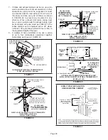
If necessary the condensate trap may be installed
up to 5’ away from the furnace. Use PVC pipe to connect
trap to furnace condensate outlet. Piping from furnace
must slope down a minimum of 1/4” per ft. toward trap.
1 -
Determine which side condensate piping will exit
the unit, location of trap, field-provided fittings and
length of PVC pipe required to reach available drain.
2 - Use a large flat head screw driver or a 1/2” drive
socket extension and remove plug (FIGURE 46)
from the cold end header box at the appropriate
location on the side of the unit. Install provided 3/4
NPT street elbow fitting into cold end header box.
Use Teflon tape or appropriate pipe dope.
NOTE -
Cold end header box drain plugs are factory
installed. Check the unused plug for tightness to
prevent leakage.
3 - Install the cap over the clean out opening at the
base of the trap. Secure with clamp. See FIGURE
54.
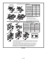
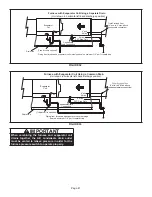
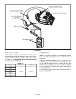
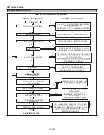
CONDENSATE TRAP AND PLUG LOCATIONS
(Unit shown in upflow position)
NOTE - In upflow applications where side return
sate trap, filter rack must be installed beyond
condensate trap or trap must be re-located to
avoid interference.
Trap
(same on
right side)
Plug
(same on left side)
1-1/2 in.
FIGURE 46
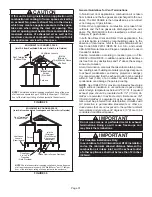
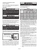
4 - Install drain trap using appropriate PVC fittings,
glue all joints. Glue the provided drain trap as
shown in FIGURE 54. Route the condensate line
to an open drain. Condensate line must maintain a
1/4” downward slope from the furnace to the drain.
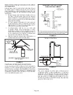
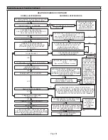
(Unit shown in upflow position with remote trap)
*5’ max.
To Drain
PVCPipeOnly
FieldProvidedVent
Min. 1” AboveCondensate
DrainConnection
1” Min.
Trap Can Be Installed a
Maximum 5’ From Furnace
2” Max.
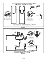
CONDENSATE TRAP LOCATIONS
*Piping from furnace must slope down a
minimum 1/4” per ft. toward trap
FIGURE 47
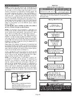
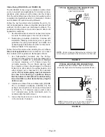
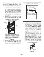
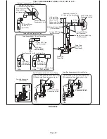
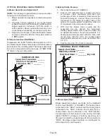
5 - FIGURE 50 and FIGURE 52 shows the furnace and
evaporator coil using a separate drain. If necessary
the condensate line from the furnace and evaporator
coil can drain together. See FIGURE 49, FIGURE
51 and FIGURE 53.
Upflow furnace (FIGURE 51)
- In upflow furnace applications the field provided
vent must be a minimum 1” to a maximum 2” length
above the condensate drain outlet connection.
Any length above 2” may result in a flooded heat
exchanger if the combined primary drain line
were to become restricted.
Horizontal furnace
(FIGURE 52)
-
In horizontal furnace applications
the field provided vent must be a minimum 4” to
a maximum 5” length above the condensate drain
outlet connection. Any length above 5” may result in
a flooded heat exchanger if the combined primary
drain line were to become restricted.
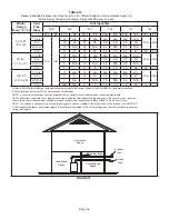
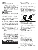
NOTE -
In horizontal applications it is recommended
to install a secondary drain pan underneath the unit
and trap assembly.
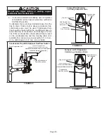
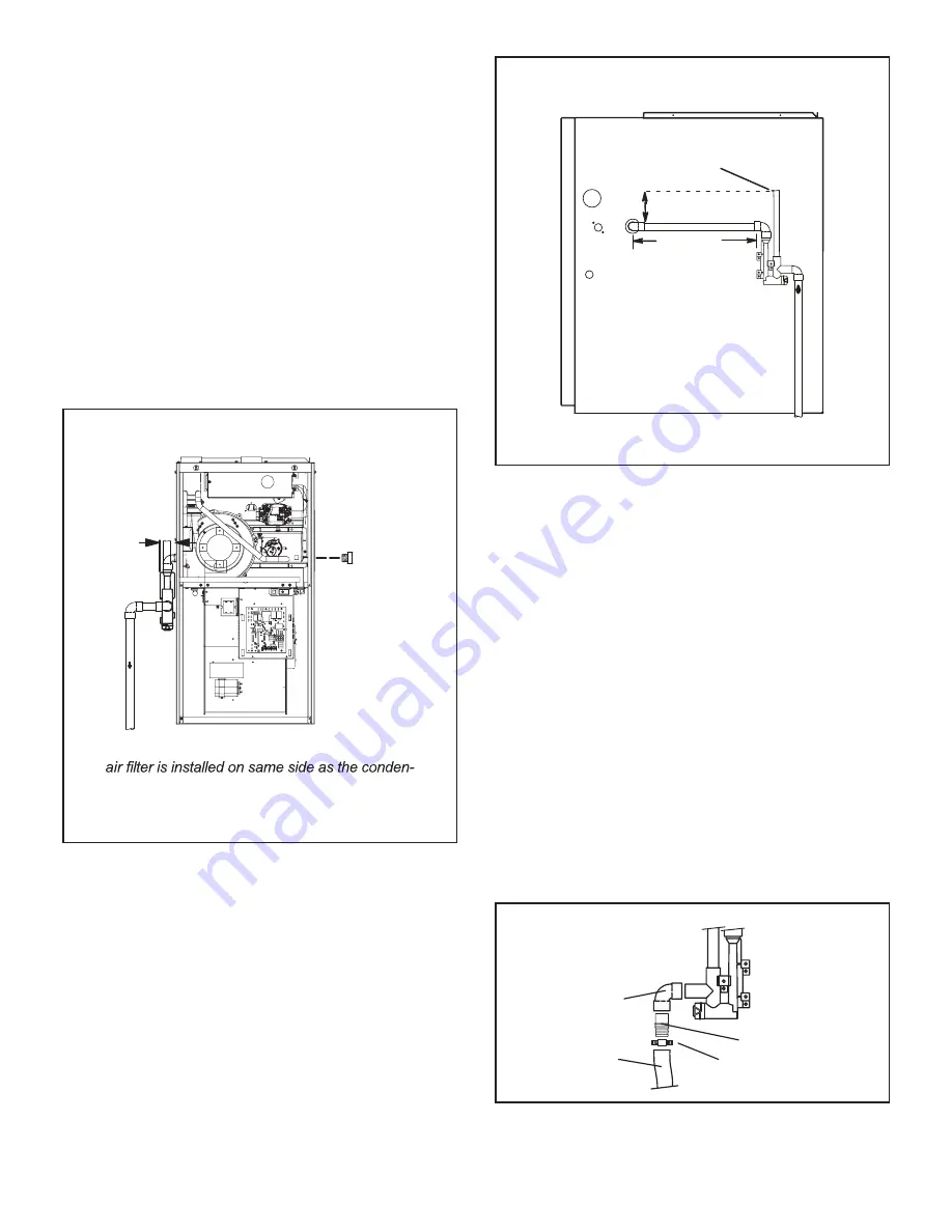
NOTE -
Appropriately sized tubing and barbed fitting
may be used for condensate drain. Attach to the
drain on the trap using a hose clamp. See FIGURE
48.
Field Provided Drain Components
Tubing
Hose Clamp
Barbed Fitting
Elbow
FIGURE 48
Содержание ML196UH030XE36B
Страница 57: ...Page 57...


