
Page 16
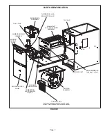
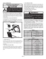
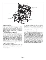
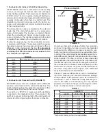
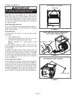
7. Combustion Air Inducer & Cold End Header Box
All ML196UHE units use a combustion air inducer (B6)
to move air through the burners and heat exchanger
during heating operation. The blower uses a shaded pole
120VAC motor. The motor operates during all heating op
-
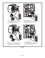
eration and is controlled by integrated control A92. Blower
operates continuously while there is a call for heat. The
integrated control will not proceed with the ignition se
-
quence until combustion air inducer operation is sensed
by the proving switches.
The combustion air inducer is installed on the cold end
header box. The cold end header box is a single piece
made of hard plastic. The box has an internal channel
where the combustion air inducer creates negative pres
-
sure at unit start up. The channel contains an orifice used
to regulate flow created by the combustion air inducer.
The box has pressure taps for the combustion air induc
-
er pressure switch hoses. The pressure switch measures
the pressure across the combustion air inducer orifice or
difference in the channel and the box.
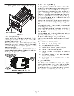
If replacement
is necessary the gaskets used to seal the box to the
vestibule panel and the combustion air inducer to the
box, must also be replaced.
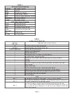
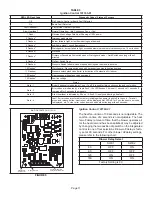
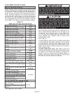
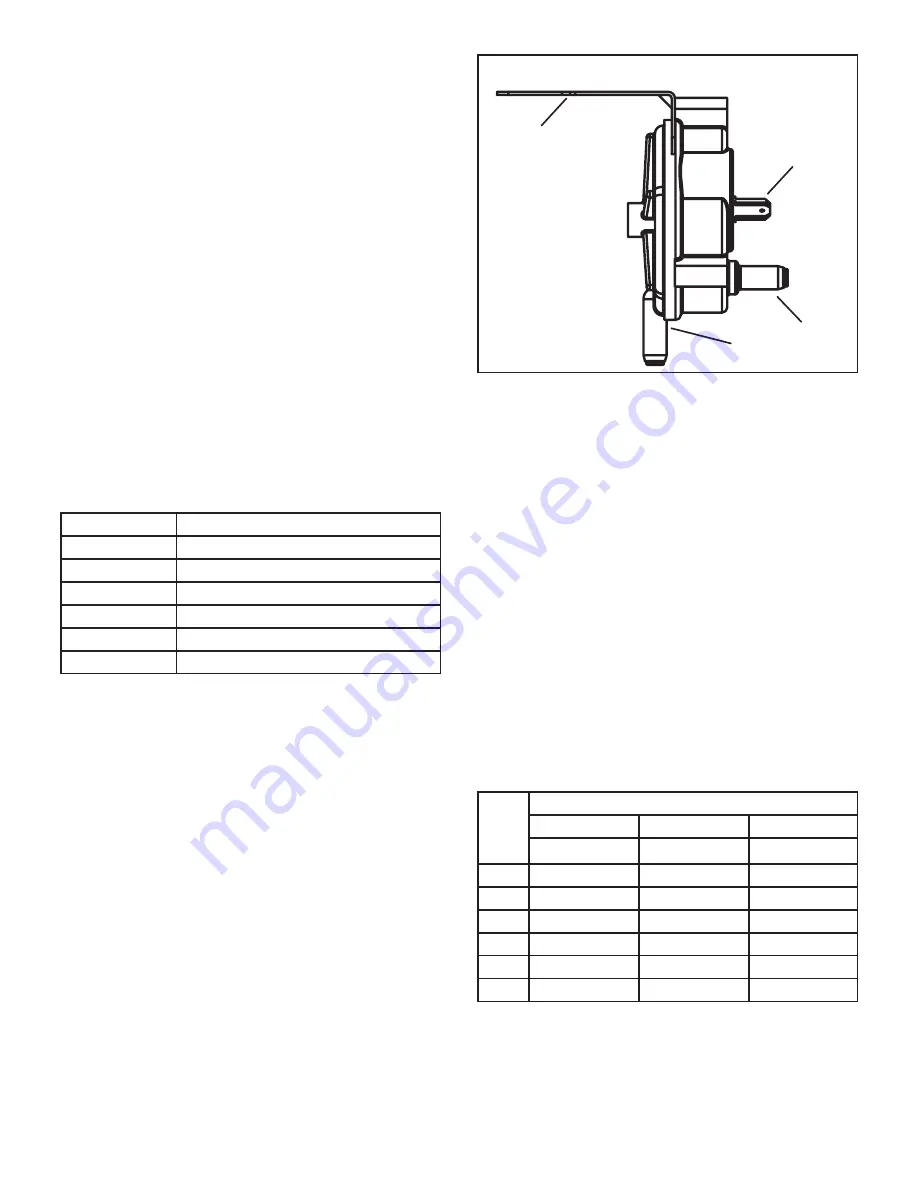
TABLE 6
Unit
Combustion Air Inducer Orifice Size
-030
0.525”
-045
0.618”
-070
0.775”
-090
0.905”
-110
1.040”
-135
1.235”
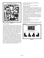
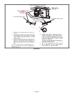
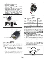
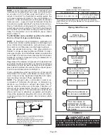
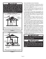
8. Combustion Air Pressure Switch (FIGURE 11)
ML196UHE series units are equipped with a differential
pressure switch located on the cold end header box. The
switch monitors across the combustion air inducer orifice
to insure proper flow through the heat exchanger.
The switch is a SPST N.O. pressure switch electrically
connected to the integrated control. The purpose of the
switch is to prevent burner operation if the combustion air
inducer is not moving enough air for proper combustion.
Pressure Switch
24VAC
TERMINALS
BRACKET
TAP
TAP
FIGURE 11
On start-up, the switch monitors whether the combustion
air inducer is operating. It closes a circuit to the integrated
control when the difference in pressure across the com
-
bustion air inducer orifice exceeds a non-adjustable facto
-
ry setting. If the switch does not successfully sense the re
-
quired differential, the switch cannot close and the furnace
cannot operate. If the flue or air inlet become obstructed
during operation, the switch senses a loss of pressure dif
-
ferential and opens the circuit to the integrated control. If
the condensate line is blocked, water will back up into the
header box and reduce the pressure differential across
the switch. The pressure switch opens if the differential
drops below the set point. See TABLE 7.
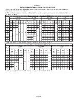
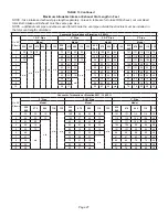
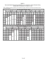
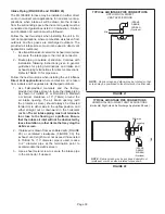
Checks of pressure differential can aid in troubleshoot
-
ing. When measuring the pressure differential, readings
should be taken at the pressure switch. See FIGURE 12
and TABLE 8. Lack of differential usually indicates prob
-
lems in the intake or exhaust piping, but may indicate
problems in the heat exchanger, condensing coil, header
boxes, combustion inducer or other components.
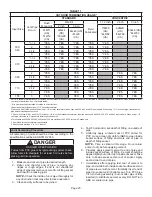
TABLE 7
Unit
Altitude Ft
0-4500
4501-7500
7501-10000
Set Point “w.c. Set Point “w.c. Set Point “w.c.
-030
-0.65
-0.65
-0.60
-045
-0.65
-0.65
-0.60
-070
-0.95
-0.65
-0.75
-090
-0.90
-0.80
-0.65
-110
-0.90
-0.85
-0.65
-135
-0.90
-0.80
-0.65
*Set point is factory set and non-adjustable.
Содержание ML196UH030XE36B
Страница 57: ...Page 57...


