background image

Page 40

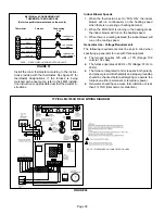
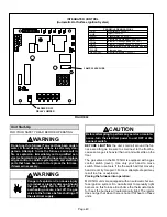
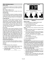
FIGURE 60

INTEGRATED CONTROL

(Automatic Hot Surface Ignition System)

TERMINAL DESIGNATIONS

HUM
LINE
XFMR
EAC
COOL
HEAT
PARK
FLAME
NEUTRALS

Humidifier (120VAC)
Input (120VAC)
Transformer (120VAC)
Electronic Air Cleaner (120VAC)
Blower − Cooling Speed (120VAC)
Blower − Heating Speed (120VAC)
Dead terminals to park alternate spd taps
Flame sensor
Neutral terminals (120VAC)

3 AMP, 32 VAC FUSE

BLOWER OFF

DELAY JUMPER

Unit Start−Up

FOR YOUR SAFETY READ BEFORE OPERATING

WARNING

Do not use this furnace if any part has been under-
water. A flood−damaged furnace is extremely dan-
gerous. Attempts to use the furnace can result in
fire or explosion. Immediately call a qualified ser-
vice technician to inspect the furnace and to replace
all gas controls, control system parts, and electrical
parts that have been wet or to replace the furnace,
if deemed necessary.


WARNING

Danger of explosion. Can cause injury
or product or property damage. Should
the gas supply fail to shut off or if
overheating occurs, shut off the gas
valve to the furnace before shutting off
the electrical supply.

CAUTION

Before attempting to perform any service or mainte-
nance, turn the electrical power to unit OFF at dis-
connect switch.

BEFORE LIGHTING

 the unit, smell all around the fur-

nace area for gas. Be sure to smell next to the floor be-
cause some gas is heavier than air and will settle on the
floor.

The gas valve on the ML195UH is equipped with a gas
control switch (lever). Use only your hand to move
switch. Never use tools. If the the switch will not move by
hand, do not try to repair it. Force or attempted repair may
result in a fire or explosion.

Placing the furnace into operation:

ML195UH units are equipped with an automatic hot sur-
face ignition system. Do not attempt to manually light
burners on this furnace. Each time the thermostat calls
for heat, the burners will automatically light. The ignitor
does not get hot when there is no call for heat on these
units.

Содержание MERIT ML195UH045XP24B

Страница 1: ...eration service or maintenance can cause property damage person al injury or loss of life Installation and service must be performed by a licensed professional installer or equivalent service agency or the gas supplier Table of Contents Unit Dimensions 2 ML195UH Parts Arrangement 3 ML195UH Gas Furnace 4 Shipping and Packing List 4 Safety Information 4 Use of Furnace as a Construction Heater 5 Gene...

Страница 2: ... TRAP CONNECTION Either Side 2 7 8 73 AIR FLOW 2 Optional External Side Return Air Filter Kit is not for use with the optional Return Air Base 1 Single side return air with transition to accommodate 20 x 25 x 1 in 508 x 635 x 25 mm cleanable air filter Required to maintain proper air velocity 2 Single side return air with optional Return Air Base 3 Bottom return air 4 Return air from both sides 5 ...

Страница 3: ...lusTM HEAT EXCHANGER ASSEMBLY CONTROL BOX includes integrated control transformer and interlock switch COMBUSTION AIR INDUCER BLOWER ACCESS DOOR BURNER ACCESS PANEL COMBUSTION AIR PRESSURE SWITCH PRIMARY LIMIT GAS VALVE BLOWER ASSEMBLY FLEXIBLE NO HUB EXHAUST COLLAR MANIFOLD COLD END HEADER BOX BAG ASSEMBLIES shipping location ...

Страница 4: ... base kit 1 Horizontal suspension kit Safety Information WARNING Improper installation adjustment alteration service or maintenance can cause property damage personal injury or loss of life Installation and service must be performed by a licensed professional in staller or equivalent service agency or the gas sup plier CAUTION As with any mechanical equipment personal injury can result from contac...

Страница 5: ...ding to local codes In addition in the United States installation must conform with the current National Electric Code ANSI NFPA No 70 The National Electric Code ANSI NFPA No 70 is available from the following ad dress National Fire Protection Association 1 Battery March Park Quincy MA 02269 In Canada all electrical wiring and grounding for the unit must be installed according to the current regul...

Страница 6: ... freezing of condensate drain system CAUTION ML195UH unit should not be installed in areas nor mally subject to freezing temperatures WARNING Product contains fiberglass wool Disturbing the insulation in this product during installation maintenance or repair will expose you to fiberglass wool Breathing this may cause lung cancer Fiberglass wool is known to the State of Cal ifornia to cause cancer ...

Страница 7: ... bined input rating of all appliances installed in that space This space also includes adjacent rooms which are not separated by a door Though an area may appear to be un confined it might be necessary to bring in outdoor air for combustion if the structure does not provide enough air by infiltration If the furnace is located in a building of tight construction with weather stripping and caulking ...

Страница 8: ...ing of all equipment in the enclosure See figures 5 and 6 When communicat ing with the outdoors through horizontal ducts each open ing shall have a minimum free area of 1 square inch 645 mm2 per 2 000 Btu 56 kW per total input rating of all equipment in the enclosure See figure 7 When ducts are used they shall be of the same cross sec tional area as the free area of the openings to which they conn...

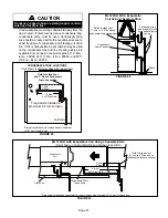
Страница 9: ...urners are operating Gas fumes which could contain carbon monoxide can be drawn into living space resulting in personal injury or death Upflow Applications The ML195UH gas furnace can be installed as shipped in the upflow position Refer to figure 10 for clearances Select a location that allows for the required clearances that are listed on the unit nameplate Also consider gas supply connections el...

Страница 10: ...per clearances to accommodate condensate trap For installations on a combustible floor do not install the furnace directly on carpeting tile or other combustible materials other than wood flooring FIGURE 10 Return Air Guidelines Return air can be brought in through the bottom or either side of the furnace installed in an upflow application If the furnace is installed on a platform with bottom retu...

Страница 11: ...sible up to 14 inches is preferred FRONT VIEW 1 Unit side return air Opening SIDE VIEW 3 1 4 83 1 23 584 Overall Maximum 584 23 3 4 19 1 22 7 16 570 Overall Maximum SIDE RETURN AIR OPENINGS Either Side 5 5 8 143 1 Minimum 11 279 2 Maximum 14 356 683 26 7 8 7 1 4 184 FURNACE FRONT AIR FLOW IF BASE IS USED WITHOUT IAQ CABINET A SINGLE RETURN AIR PLENUM MUST COVER BOTH UNIT AND RETURN AIR BASE OPENIN...

Страница 12: ...sheet metal straps may be used to suspend the unit from roof rafters or ceiling joists When straps are used to suspend the unit in this way support must be provided for both the ends The straps must not interfere with the plenum or exhaust piping installation Cooling coils and supply and return air plenums must be supported separately FIGURE 16 HORIZONTAL SUSPENSION KIT Bracket typical Metal Strap...

Страница 13: ... access panel should be installed in the supply air duct The access panel should be large enough to permit inspection of the heat exchanger The furnace access panel must al ways be in place when the furnace is operating and it must not allow leaks Return Air Plenum NOTE Return air must not be drawn from a room where this furnace or any other gas fueled appliance i e water heater or carbon monoxide...

Страница 14: ... PVC or CPVC Transition Cement IMPORTANT ML195UH exhaust and intake connections are made of PVC Use PVC primer and solvent cement when using PVC vent pipe When using ABS vent pipe use transitional solvent cement to make connections to the PVC fittings in the unit Use PVC primer and solvent cement or ABS solvent cement meeting ASTM specifications refer to Table 2 As an alter nate use all purpose ce...

Страница 15: ...should be done according to the specifications outlined in ASTM D 2855 DANGER DANGER OF EXPLOSION Fumes from PVC glue may ignite during system check Allow fumes to dissipate for at least 5 minutes before placing unit into operation 1 Measure and cut vent pipe to desired length 2 Debur and chamfer end of pipe removing any ridges or rough edges If end is not chamfered edge of pipe may remove cement ...

Страница 16: ... home make provisions for draining conden sate collection trap and lines CHIMNEY OR GAS VENT Check sizing for water heater only FURNACE Replaced by ML195 WATER HEATER OPENINGS To Adjacent Room If an ML195UH furnace replaces a furnace which was commonly vented with another gas appliance the size of the existing vent pipe for that gas ap pliance must be checked Without the heat of the original furna...

Страница 17: ...n an upflow applica tion a transition must be applied at the exhaust collar in order to properly step to the larger diameter vent pipe Contact the Application Department for more information concerning sizing of vent systems which include multiple pipe sizes FIGURE 20 Exhaust Pipe NOTE Exhaust pipe MUST be glued to furnace exhaust fittings NOTE All horizontal runs of exhaust pipe must slope back t...

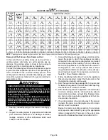
Страница 18: ...118 117 98 98 94 6 56 41 19 90 90 68 33 113 112 93 93 89 7 51 36 14 85 85 63 28 108 107 88 88 84 8 46 31 n a 80 80 58 23 103 102 83 83 79 9 41 26 75 75 53 18 98 97 78 78 74 10 36 21 70 70 48 13 93 92 73 73 69 Standard Termination Elevation 4500 10 000 ft Number Of 90 Elbows Used 2 Pipe 2 1 2 Pipe 3 Pipe Model Model Model 045 070 090 110 135 045 070 090 110 135 045 070 090 110 135 1 81 66 44 n a n ...

Страница 19: ...5 75 59 24 91 91 84 84 75 8 38 23 n a 70 70 54 19 86 86 79 79 70 9 33 18 65 65 49 14 81 81 74 74 65 10 28 13 60 60 44 n a 76 76 69 69 60 Concentric Termination Elevation 4501 10 000 ft Number Of 90 Elbows Used 2 Pipe 2 1 2 Pipe 3 Pipe Model Model Model 045 070 090 110 135 045 070 090 110 135 045 070 090 110 135 1 73 58 42 n a n a 105 105 89 54 n a 121 121 114 114 105 2 68 53 37 100 100 84 49 116 1...

Страница 20: ...E When transitioning up in pipe size use the shortest length of 2 PVC pipe possible FIGURE 23 2 TRANSITION 2 SIDE VIEW 2 2 2 2 or TYPICAL EXHAUST AND INTAKE PIPE CONNECTIONS IN HORIZONTAL DIRECT OR NON DIRECT VENT APPLICATIONS RIGHT HAND DISCHARGE SHOWN 3 2 45 MAX 45 MAX DO NOT transition from smaller to larger pipe in horizontal runs of exhaust pipe EXHAUST 12 max 2 2 2 or 2 INTAKE 2 TRANSITION 2...

Страница 21: ...CREEN Provided NOTE Debris screen and elbow may be rotated so that screen may be positioned to face forward or to either side FIGURE 25 TYPICAL AIR INTAKE PIPE CONNECTIONS HORIZONTAL NON DIRECT VENT APPLICATIONS Horizontal Right Hand Air Discharge Application Shown INTAKE DEBRIS SCREEN Provided OR NOTE Debris screen may be positioned straight out preferred or with an elbow rotated to face down cou...

Страница 22: ...sign temperature is below 32 F 0 C exhaust piping should be insulated with 1 2 13mm Ar maflex or equivalent when run through unheated space Do not leave any surface area of exhaust pipe open to out side air exterior exhaust pipe should be insulated with 1 2 13mm Armaflex or equivalent In extreme cold cli mate areas 3 4 19mm Armaflex or equivalent may be necessary Insulation on outside runs of exha...

Страница 23: ...ly inlet Clearance above paved sidewalk or paved driveway located on public property Clearance under veranda porch deck or balcony 12 Equal to or greater than soffit depth 3 feet 9m 12 3 feet 9m within a height 15 feet 4 5m above the meter regulator assembly 3 feet 9m 6 inches 152mm for appliances 10 000 Btuh 3kw 12 inches 305mm for appliances 10 000 Btuh 3kw and 100 000 Btuh 30kw 36 inches 9m for...

Страница 24: ...ove paved sidewalk or paved driveway located on public property Clearance under veranda porch deck or balcony 12 7 feet 2 1m 3 feet 9m within a height 15 feet 4 5m above the meter regulator assembly 3 feet 9m 6 inches 152mm for appliances 10 000 Btuh 3kw 9 inches mm for appliances 10 000 Btuh 3kw and 50 000 Btuh 15 kw 12 inches 305mm for ap pliances 50 000 Btuh 15kw 6 inches 152mm for appliances 1...

Страница 25: ...45 and 070 2 51mm 2 1 2 64mm 3 76mm 1 1 2 38mm 090 2 51mm 110 2 51mm 135 3 76mm 2 51mm NOTE Care must be taken to avoid recirculation of ex haust back into intake pipe FIGURE 28 UNCONDITIONED ATTIC SPACE 1 2 13mm FOAM INSULATION IN UNCONDITIONED SPACE SIZE TERMINATION PIPE PER TABLE 6 3 76mm MAX 12 305mm ABOVE AVERAGE SNOW ACCUMULATION 3 76mm OR 2 51mm PVC PROVIDE SUPPORT FOR INTAKE AND EXHAUST LI...

Страница 26: ...xtend a maximum of 12 inches 305mm for 2 PVC and 20 inches 508mm for 3 76mm PVC beyond the outside wall Intake piping should be as short as possible See figures 29 and 30 6 On field supplied terminations a minimum distance between the end of the exhaust pipe and the end of the intake pipe without a termination elbow is 8 and a minimum distance of 6 with a termination elbow See figures 29 and 30 7 ...

Страница 27: ... provided on 71M80 44W92 kits for ML195UH045P24B 070P24B 070P36B EXHAUST VENT FIGURE 34 EXHAUST VENT INTAKE AIR 5 1 2 140mm Front View 12 305mm 5 127mm 18 MAX 457mm EXHAUST VENT INTAKE AIR OPTIONAL VENT TERMINATION FOR MULTIPLE UNIT INSTALLATION OF DIRECT VENT WALL TERMINATION KIT 22G44 44J40 30G28 or 81J20 Inches mm Side View 12 305mm Min above grade or average snow accumulation optional intake e...

Страница 28: ...ipe is less than 12 in 305 mm above snow accumulation or other obstructions field fabricated piping must be installed FIGURE 38 ÉÉÉÉÉÉÉÉÉÉÉÉ 12 305 mm Minimum Above Grade or Average Snow Accumulation 1 2 13 mm FOAM INSULATION Field Furnished 5 127 mm 5 1 2 140 mm EXHAUST AIR INTAKE AIR GRADE 12 305 mm INTAKE AIR EXHAUST AIR GRADE WALL SUPPORT 12 305 mm Minimum Above Grade or Average Snow Accumulat...

Страница 29: ...aust piping may extend a maximum of 12 inches 305mm for 2 PVC and 20 inches 508mm for 3 76mm PVC beyond the outside wall See figure 41 FIGURE 40 NON DIRECT VENT ROOF TERMINATION KIT 15F75 or 44J41 UNCONDITIONED ATTIC SPACE 3 76mm OR 2 51mm PVC PROVIDE SUPPORT FOR EXHAUST LINES 12 305mm ABOVE AVE SNOW ACCUMULATION SIZE TERMINATION PIPE PER TABLE 6 1 2 13mm FOAM INSULATION FIGURE 41 1 2 13mm ARMAFLE...

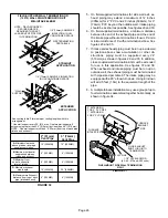
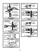
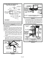
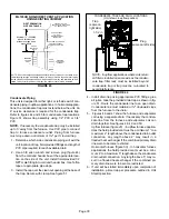
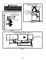
Страница 30: ...box at the appropriate loca tion on the side of the unit Install field provided 1 2 NPT male fitting into cold end header box Use Teflon tape or appropriate pipe dope 3 Install the cap over the clean out opening at the base of the trap Secure with clamp See figure 51 FIGURE 44 CONDENSATE TRAP AND PLUG LOCATIONS Unit shown in upflow position NOTE In upflow applications where side return air filter ...

Страница 31: ...osition with remote trap 5 max To Drain PVC Pipe Only Field Provided Vent Min 1 Above Condensate Drain Connection 1 Min Trap Can Be Installed a Maximum 5 From Furnace Piping from furnace must slope down a minimum of 1 4 per ft toward trap 2 Max FIGURE 46 Field Provided Vent 1 min to 2 Max above condensate drain connection Drain Condensate trap and evaporator coil drain separately as shown Condensa...

Страница 32: ...ection From Evaporator Coil To Drain Optional Overflow Switch FIGURE 49 ML195UH with Evaporator Coil Using a Common Drain Field Provided Vent 1 min to 2 Max above condensate drain connection Evaporator Drain Line Vent Required Condensate Drain Connection FIGURE 50 Condensate Drain Connection ML195UH with Evaporator Coil Using a Common Drain Unit shown in horizontal left hand discharge position Fie...

Страница 33: ... inch PVC Not Furnished 1 2 inch PVC Pipe Not Furnished Drain Assembly for 3 4 inch Drain Pipe 90 Street Elbow 1 2 inch PVC Not Furnished Condensate Drain Connection In Unit Adapter 1 2 inch slip X 1 2 inch mpt Not Furnished Condensate Drain Connection In Unit Vent To Drain Condensate Drain Connection In Unit Drain Trap Assembly with 3 4 inch Piping Vent To Drain Furnished Optional Condensate Drai...

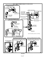
Страница 34: ...densate 5 A 1 8 N P T plugged tap or pressure post is located on the gas valve to facilitate test gauge connection See figure 61 6 In some localities codes may require installation of a manual main shut off valve and union furnished by in staller external to the unit Union must be of the ground joint type IMPORTANT Compounds used on threaded joints of gas piping must be resistant to the actions of...

Страница 35: ...ows Grommet FIGURE 53 Horizontal Applications Possible Gas Piping Configurations GROUND JOINT UNION DRIP LEG MANUAL MAIN SHUT OFF VALVE GROUND JOINT UNION DRIP LEG MANUAL MAIN SHUT OFF VALVE GROUND JOINT UNION DRIP LEG MANUAL MAIN SHUT OFF VALVE Horizontal Application Left Side Air Discharge Horizontal Application Right Side Air Discharge NOTE BLACK IRON PIPE ONLY TO BE ROUTED INSIDE OF CABINET FI...

Страница 36: ... indicated in the general venting re quirements section WARNING CARBON MONOXIDE POISONING HAZARD Failure to follow the steps outlined below for each appliance connected to the venting system being placed into operation could result in carbon mon oxide poisoning or death The following steps shall be followed for each ap pliance connected to the venting system being placed into operation while all o...

Страница 37: ...the wires will be long enough for servicing at a later date Make sure that thermostat wire is long enough to facilitate future removal of blower for service Complete the wiring connections to the equipment Use the provided unit wiring diagram and the field wiring diagram shown in figure 58 Use 18 gauge wire or larger that is suit able for Class II rating for thermostat connections Electrically gro...

Страница 38: ...eating speed when there is no cooling or heating demand 2 When the ML195UH is running in the heating mode the indoor blower will run on the heating speed 3 When there is a cooling demand the indoor blower will run on the cooling speed Generator Use Voltage Requirements The following requirements must be kept in mind when specifying a generator for use with this equipment D The furnace requires 120...

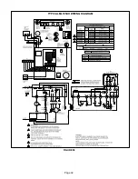
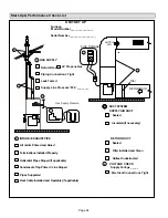
Страница 39: ...Page 39 TYPICAL ML195UH WIRING DIAGRAM FIGURE 59 ...

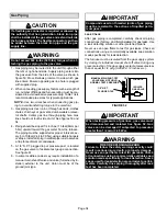
Страница 40: ...xplosion Can cause injury or product or property damage Should the gas supply fail to shut off or if overheating occurs shut off the gas valve to the furnace before shutting off the electrical supply CAUTION Before attempting to perform any service or mainte nance turn the electrical power to unit OFF at dis connect switch BEFORE LIGHTING the unit smell all around the fur nace area for gas Be sure...

Страница 41: ...all electrical power to to the unit 11 Set the thermostat to desired setting NOTE When unit is initially started steps 1 through 11 may need to be repeated to purge air from gas line 12 If the appliance will not operate follow the instructions Turning Off Gas to Unit and call your service techni cian or gas supplier Turning Off Gas to Unit 1 Set the thermostat to the lowest setting 2 Turn off all ...

Страница 42: ...and allow 5 minutes for unit to reach steady state 3 While waiting for the unit to stabilize observe the flame Flame should be stable and should not lift from burner Natural gas should burn blue 4 After allowing unit to stabilize for 5 minutes record manifold pressure and compare to value given in table 9 NOTE Shut unit off and remove manometer as soon as an accurate reading has been obtained Take...

Страница 43: ...iances both in operation and those not in operation are connected to the venting system being tested If the venting system has been installed improperly or if provisions have not been made for sufficient amounts of combustion air corrections must be made as outlined in the previous section 1 Seal any unused openings in the venting system 2 Visually inspect the venting system for proper size and ho...

Страница 44: ...ng for loose connections 2 Check for the correct voltage at the furnace furnace operating Correct voltage is 120VAC 10 3 Check amp draw on the blower motor with blower ac cess panel in place Motor Nameplate__________Actual__________ HEAT FAN OFF TIME IN SECONDS To adjust fan off timing reposition jumper across pins to achieve desired setting NO JUMPER FIGURE 62 60 90 120 180 60 90 120 180 60 90 12...

Страница 45: ... 350 740 295 585 240 505 220 0 80 790 325 670 275 510 225 455 205 0 90 735 310 575 255 460 220 390 195 ML195UH070XP36B PERFORMANCE Less Filter External Static Pressure in w g Air Volume Watts at Various Blower Speeds High Medium High Medium Low Low cfm Watts cfm Watts cfm Watts cfm Watts 0 00 1585 685 1340 585 1095 480 880 380 0 10 1560 665 1320 565 1085 470 885 375 0 20 1515 630 1300 540 1080 460...

Страница 46: ...75 1590 840 1505 710 1280 590 0 90 1730 1150 1570 790 1470 660 1250 540 1630 1135 1490 685 1460 685 1235 565 ML195UH135XP60D PERFORMANCE Less Filter External Static Pressure in w g Air Volume Watts at Different Blower Speeds Bottom Return Air Side Return Air with Optional Return Air Base Return Air from Both Sides or Return Air from Bottom and One Side Single Side Return Air Air volumes in bold re...

Страница 47: ... cap Cleaning Heat Exchanger If cleaning the heat exchanger becomes necessary follow the below procedures and refer to figure 1 when disassem bling unit Use papers or protective covering in front of fur nace while removing heat exchanger assembly 1 Turn off electrical and gas supplies to the furnace 2 Remove the burner access panel 3 Mark all gas valve wires and disconnect them from valve 4 Remove...

Страница 48: ...r box 40 Secure burner assembly to vestibule panel using four existing screws Burners are self aligning to center of clam shells 41 Reconnect gas supply line to gas valve 42 Reconnect flame roll out switch wires 43 Reconnect sensor wire and reconnect 2 pin plug from ignitor 44 Reconnect wires to gas valve 45 Replace the blower compartment access panel 46 Refer to instruction on verifying gas and e...

Страница 49: ...xt to the furnace may obstruct the combustion air supply This could cause incomplete combustion and the production of carbon monoxide gas Ignition Control Board Diagnostic Codes DIAGNOSTIC CODES Make sure to Identify LED S Correctly LED 1 Red LED 2 Green DESCRIPTION SIMULTANEOUS SLOW FLASH SIMULTANEOUS SLOW FLASH Power on Normal operation Also signaled during cooling and continuous fan SIMULTANEOU...

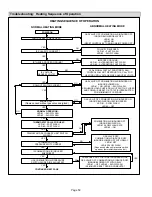
Страница 50: ...OWER ON HEATING SPEED LED 1 SLOW FLASH LED 2 OFF GAS VALVE OFF COMBUSTION AIR INDUCER OFF INDOOR BLOWER OFF WITH DELAY LED 1 OFF LED 2 SLOW FLASH Sequence holds until pressure switch opens or thermostat resets control NO NO YES YES IS VOLTAGE ABOVE 90 VOLTS LEDs SIGNAL FAST ALTERNATING FLASH CONTROL WILL NOT RESPOND TO A CALL FOR HEATING UNTIL VOLTAGE RISES ABOVE 95 VOLTS NO NO NO IS COMBUSTION AI...

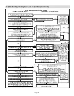
Страница 51: ...IS 60 MINUTE RESET PERIOD COMPLETE YES 4 SECONDS YES HAS CONTROL RESET IGNITION SEQUENCE FOUR TIMES FLAME SIGNAL 1 5 MICROAMPS OR GREATER YES YES YES ROLLOUT SWITCH CLOSED GAS VALVE POWER OFF COMBUSTION AIR INDUCER POWER ON INDOOR BLOWER ON LED 1 ON LED 2 SLOW FLASH SEQUENCE HOLDS UNTIL ROLLOUT SWITCH IS RESET AND MAIN POWER IS INTERRUPTED OR THERMOSTAT IS CYCLED OFF ON FOR 1 SEC MINIMUM YES THERM...

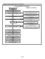
Страница 52: ...ITCH CLOSED LED SLOW FLASH RATE REMAINS UNCHANGED THROUGHOUT COOLING CYCLE THERMOSTAT CALLS FOR COOLING COMPRESSOR CONTACTOR AND SYSTEM FAN ENERGIZED WITH 2 SECOND DELAY COOLING SPEED EAC TERM ENERGIZED COMPRESSOR OFF THERMOSTAT OPENS SYSTEM FAN AND EAC TERM OFF WITH 45 SECOND DELAY NO NO GAS VALVE OFF COMBUSTION AIR INDUCER ON INDOOR BLOWER ON SIGNAL ROLL OUT SWITCH OPEN AT LED SEQUENCE HOLDS UNT...

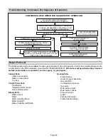
Страница 53: ...FAN REMAINS ON HEATING SPEED HUM TERM DE ENERGIZES WITH COMB AIR INDUCER Repair Parts List The following repair parts are available through Lennox dealers When ordering parts include the complete furnace model number listed on the CSA nameplate Example ML195UH045XP24B 01 All service must be performed by a licensed professional installer or equivalent service agency or gas supplier Cabinet Parts Up...

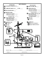
Страница 54: ...Installed Properly Pipes Supported Condensate Trap Primed Line Sloped Heat Cable Installed and Operable if applicable 2 2 2 1 Horizontal Pipes Sloped if applicable UNIT SET UP 3 4 Flter RETURN AIR Furnace Model Number_______________ Serial Number_________________ 3 DUCT SYSTEM SUPPLY AIR DUCT Sealed Insulated if necessary RETURN DUCT Sealed Filter Installed and Clean Grilles Unobstructed 4 VOLTAGE...

Страница 55: ...ATIC 5 Supply External Static _______ Return External Static ______ Total External Static _______ CONDENSATE LINE 6 Leak Free VENT PIPE 7 Leak Free COOLING MODE INDOOR BLOWER AMPS______ 3 TEMPERATURE DROP Return Duct Temperature _________ Supply Duct Temperature _ _______ Temperature Drop _________ 4 DRAIN LINE 8 Leak Free THERMOSTAT Adjusted and Programmed Explained Operation to Owner 9 SUPPLY AI...

Страница 56: ... eight 8 feet above grade di rectly in line with the exhaust vent terminal for the hori zontally vented gas fueled heating appliance or equipment The sign shall read in print size no less than one half 1 2 inch in size GAS VENT DIRECT LY BELOW KEEP CLEAR OF ALL OBSTRUC TIONS 4 INSPECTION The state or local gas inspector of the side wall horizontally vented gas fueled equipment shall not approve th...

Отзывы: