background image

Page 9

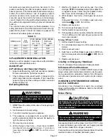
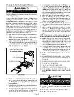
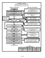
INTEGRATED IGNITION CONTROL 97L48
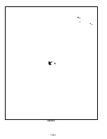
FIGURE 6

J58

J156

TABLE 1

IGNITION CONTROL 97L48 TERMINAL DESIGNATIONS

ACB COOL

blower −  cooling speed (line voltage)

ACB HEAT

blower − heating speed (line voltage)

PARK

alternate blower speeds

ACB LOW

continuous low speed

ACC

accessory terminal (line voltage)

TX

line voltage to transformer

HOT

120vac hot

HTG ACC

heat only accessory (line voltage)

NEUTRAL

120vac neutral

24VAC HOT

24vac return from transformer

24VAC RTN

24vac from transformer

FLAME SENSE

flame sense terminal

TABLE 2

IGNITION CONTROL 97L48 J156 TERMINAL

 DESIGNATIONS

PIN #

FUNCTION

1

Ignitor

2

Not Used

3

Ignitor Neutral

4

Combustion Air Inducer Line Voltage

5

Not Used

6

Combustion Air Inducer Neutral

TABLE 3

IGNITION CONTROL 97L48 J58 TERMINAL

 DESIGNATIONS

PIN #

FUNCTION

1

Primary Limit In

2

Gas Valve Common

3

Roll Out Switch Out

4

Gas Valve 24V

5

Pressure Switch In

6

Pressure Switch and Primary Limit Out

7

Not Used

8

Roll Out Switch In

9

Ground

a−Electronic Ignition (See Figure 8)

On a call for heat the SureLight

®

 control monitors the com-

bustion air inducer prove switch. The control will not begin
the heating cycle if the prove switch is closed (by−passed).
Once the proving switch is determined to be open, the com-
bustion air inducer is energized. When the differential in the
prove switch is great enough, the prove switch closes and a
15−second pre−purge begins. If the prove switch is not
proven within 2−1/2 minutes, the control goes into Watch-
guard−Pressure Switch mode for a 5−minute re−set period.
 After the 15−second pre−purge period, the SureLight ignitor
warms up for 20 seconds during which the gas valve opens
at 19 seconds for a 4−second trial for ignition. The ignitor
stays energized during the 4−second ignition trial until
flame is sensed. If ignition is not proved during the 4−sec-
ond period, the control will try four more times with an inter
purge and warm−up time between trials of 35 seconds. Af-
ter a total of five trials for ignition (including the initial trial),
the control goes into Watchguard−Flame Failure mode. Af-
ter a 60−minute reset period, the control will begin the igni-
tion sequence again.
The SureLight control board has an added feature that pro-
longs the life of the ignitor. After a successful ignition, the
SureLight control utilizes less power to energize the ignitor
on successive calls for heat. The control continues to ramp
down the voltage to the ignitor until it finds the lowest
amount of power that will provide a successful ignition. This
amount of power is used for 255 cycles. On the 256th call
for heat, the control will again ramp down until the lowest
power is determined and the cycle begins again.

Содержание G50UHi Series

Страница 1: ...ned in this manual are presented as a recom mendation only and do not supersede or replace local or state codes In the absence of local or state codes the guidelines and procedures outlined in this ma...

Страница 2: ...gle 44J22 Ten Pack 66K63 1 16 x 25 x 1 406 x 635 x 25 EZ Filter Base Catalog Number Ship Wt 73P55 6 lbs 3 kg 73P56 7 lbs 3 kg 73P56 7 lbs 3 kg Base Dimensions H x W x D 4 x 14 1 4 x 28 5 8 in 102 x 36...

Страница 3: ...8 m 15M22 15M22 LPG Propane Kit 0 7500 ft 0 2286 m 45L60 45L60 p 7501 10 000 ft 2286 3048 m 47M81 47M81 Horizontal Support Frame Kit Shipping Weight 56J18 18 lbs 8 kg 56J18 18 lbs 8 kg Relay Kit 56L68...

Страница 4: ...060 500 475 985 465 445 875 415 390 790 375 330 690 325 290 525 250 225 0 9 225 935 440 435 930 440 435 885 420 410 825 390 390 740 350 350 675 320 295 510 240 235 NOTES All air data is measured exter...

Страница 5: ...375 650 420 1075 505 290 0 4 100 2055 970 1015 1945 920 890 1825 860 775 1680 790 645 1525 720 545 1375 650 455 1075 505 310 0 5 125 2010 950 1025 1895 895 890 1810 855 810 1680 795 690 1515 715 580 1...

Страница 6: ...Page 6 FIGURE 1...

Страница 7: ...HORIZONTAL POSITION BLOWER ACCESS PANEL HEAT EXCHANGER ASSEMBLY BURNER ASSEMBLY COMBUSTION AIR INDUCER SURELIGHT CONTROL BOARD GAS VALVE BURNER ACCESS PANEL BLOWER ASSEMBLY PRIMARY LIMIT BLOWER CONTRO...

Страница 8: ...utions will help to avoid control exposure to electrostatic dis charge by putting the furnace the control and the technician at the same electrostatic poten tial Neutralize electrostatic charge by tou...

Страница 9: ...tion air inducer is energized When the differential in the prove switch is great enough the prove switch closes and a 15 second pre purge begins If the prove switch is not proven within 2 1 2 minutes...

Страница 10: ...NEOUS FAST FLASH SIMULTANEOUS FAST FLASH Normal operation signaled when heating demand initiated at thermostat SLOW FLASH ON Primary or secondary limit switch open Limit must close within 3 minutes or...

Страница 11: ...ic or electro mechanical thermostats without modification Each time power is applied to the furnace the ignition con trol performs a selfcheck The SureLight ignitor is made of durable silicon nitride...

Страница 12: ...ge to the ignitor until it finds the lowest amount of power that will provide a successful ignition This amount of power is used for 255 cycles On the 256th call for heat the control will again ramp d...

Страница 13: ...ge before re moving blower control module cover Failure to wait may cause personal injury or death Remove the cover panel from the module to access the se lector jumpers There are five selector pins i...

Страница 14: ...C Ramp A 6 Ignitor The SureLight ignitor is made of durable silicon nitride Ig nitor longevity is enhanced by controlling voltage to the ig nitor The board finds the lowest ignitor temperature which...

Страница 15: ...cut out from the side of the cabinet See figure 15 Use the two provided sheet metal screws to install the cut out on the top cap to cover the original flue outlet open ing Combustion Air Inducer Upfl...

Страница 16: ...ir blower and closes the gas valve The limit automatically resets when unit temperature returns to normal G50UHi 1 through 6 units use a surface type limit factory set to open at 125 F G50UHi 7 and la...

Страница 17: ...eywell Gas Valve Turn knob on gas valve clockwise to OFF Do not force See figure 18 7 Wait five 5 minutes to clear out any gas If you then smell gas STOP Immediately call your gas supplier from a neig...

Страница 18: ...n checked and adjusted check manifold pressure Move pressure gauge to outlet pres sure tap located on unit gas valve GV1 Checks of man ifold pressure are made as verification of proper regulator ad ju...

Страница 19: ...a tion Current passes from the sensor through the flame to ground to complete a safety circuit TABLE 17 Flame Signal in Microamps Ignition Control Normal Low Drop Out 97L48 0 61 0 21 0 60 0 20 69M15 0...

Страница 20: ...onnect the other end of manometer to the return duct as above For systems with non ducted returns leave the other end of the manometer open to the at mosphere 3 With only the blower motor running and...

Страница 21: ...aning is accomplished Reverse drill and slowly work the cable out of opening 8 Repeat procedure for each heat exchanger section 9 After each of the top heat exchanger sections has been cleaned insert...

Страница 22: ...Page 22 VII WIRING AND SEQUENCE OF OPERATION...

Страница 23: ...s into 5 minute Watchguard Pressure Switch delay Once S18 closes a 15 second pre purge follows 4 SureLight control A92 energizes ignitor A 20 second warm up period begins 5 Gas valve opens for a 4 sec...

Страница 24: ...WITH DELAY LED 1 OFF LED 2 SLOW FLASH Sequence holds until PROVE switch closes or thermostat resets control NO NO YES NO IS THERE PROPER GROUND IS VOLTAGE ABOVE 75 VOLTS LED 1 AND LED 2 ALTERNATING FA...

Страница 25: ...CER OFF INDOOR BLOWER OFF WITH DELAY LED 1 ALT SLOW FLASH LED 2 ALT SLOW FLASH IS 60 MINUTE RESET PERIOD COMPLETE YES 4 SECONDS YES HAS CONTROL RESET IGNITION SEQUENCE FOUR TIMES FLAME SIGNAL NORMAL S...

Страница 26: ...TOR AND SYSTEM FAN ENERGIZED AFTER DELAY COOL SPEED AND ELECTRONIC AIR CLEANER TERMINAL IS ENERGIZED Control board 69M15 2 second delay Control board 97L48 no delay COMPRESSOR OFF THERMOSTAT OPENS COO...

Страница 27: ...OPENS COMBUSTION AIR INDUCER AND HEATING ACCESSORY TERMINAL ARE DE ENERGIZED INDOOR BLOWER SWITCHES TO COOL SPEED THERMOSTAT OPENS INDOOR BLOWER SWITCHES TO CONTINUOUS BLOWER ELECTRONIC AIR CLEANER T...

Страница 28: ...pen ACTION 1 Manually reset the roll out switch by pushing the top button ACTION 2 Determine the cause of the roll out switch activation before leaving furnace code LED 1 O 1 2 2 Roll out switch failu...

Страница 29: ...1 Alternating Fast Flash LED 2 Alternating Fast Flash 2 1 2 Broken or failed ignitor ACTION 1 Unplug ignitor and read resistance across ignitor If resistance does not read be tween 10 9 and 19 7 ohms...

Страница 30: ...with a heating demand Diagnostic lights flash the pressure switch failure code 2 5 minutes after heating demand 4 1 2 Prove switch does not close due to obstructions in the pressure lines ACTION 1 Re...

Страница 31: ...ure switch code LED 1 Off LED 2 Slow Flash 6 1 1 Low pressure differential at the prove switch ACTION 1 Check for restricted exhaust vent Remove all blockage ACTION 2 Check for proper vent sizing See...

Страница 32: ...ash 6 3 3 Insufficient flow through the heat exchanger caused by a sooted or restricted heat exchanger ACTION 1 Check for sooting deposits or other restrictions in the heat exchanger assembly Clean as...

Страница 33: ...lash 7 1 2 Sense rod is contaminated ACTION 1 Check sense rod for contamination or coated surface Clean the sense rod with steel wool or replace sensor DO NOT USE SAND PA PER TO CLEAN ROD SAND PAPER W...

Страница 34: ...t lead from ACB Cool to 120HOT terminal D Make sure blower access panel is replaced properly to close door interlock switch and energize SureLight control board D Repeat with ACB Heat and ACB Low lead...

Страница 35: ...ize SureLight control board D Check for proper demand from thermostat Is motor operating properly Recheck all wiring connections CHECK BLOWER CONTROL MODULE Proper blower control module must be instal...

Отзывы: