background image

Page 26

506727−01

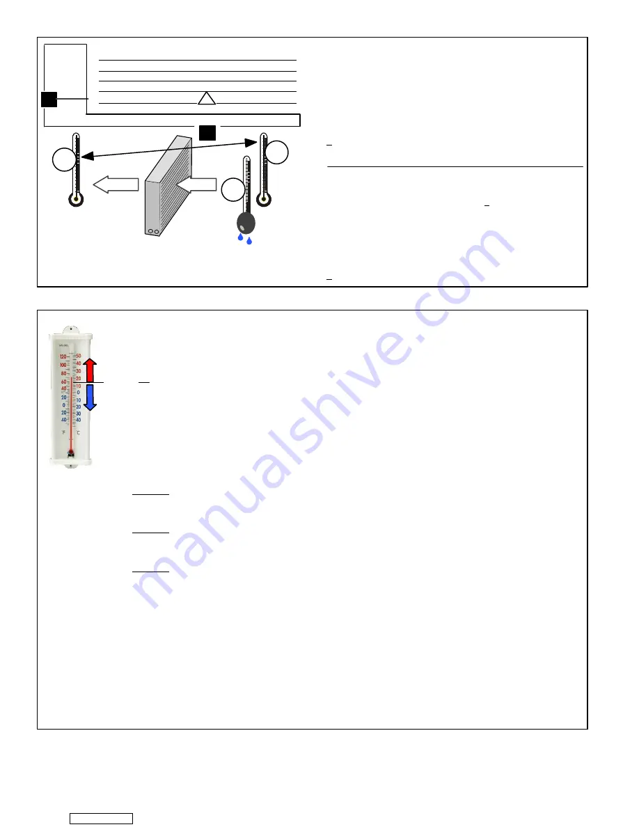
1. Determine the desired 

D

T

Measure entering air temper-

ature using dry bulb (

A

) and wet bulb (

B

). 

D

T

 is the intersect-

ing value of 

A

 and

 B

 in the table (see triangle).

2. Find temperature drop across coil

Measure the coil’s dry

bulb entering and leaving air temperatures (

A

 and 

C

). Tem-

perature Drop Formula: (

T

Drop

) = 

A

 minus 

C

.

3. Determine if fan needs adjustment

If the difference between

the measured 

T

Drop

 and the desired 

D

T


(T

Drop

D

T) 

is within

+3º, no adjustment is needed. See examples: Assume 

D

T

 =

15 and 

A

 temp. = 72º, these 

temperatures would necessi-

tate stated actions:

  T

Drop

D

T

=

ºF

ACTION

53º

 19

15

=

4

Increase the airflow

58º

14

15

=

−1

(3º range) no change

62º

10

15

=

−5

Decrease the airflow

4. Adjust the fan speed

See indoor unit instructions to in-

crease/decrease fan speed.

Changing air flow affects all temperatures; recheck tempera-
tures to confirm that the temperature drop and 

D

T are within

+3º.

D

T

80

24 24 24 23 23 22 22 22 20 19 18 17 16 15

78

23 23 23 22 22 21 21 20 19 18 17 16 15 14

76

22 22 22 21 21 20 19 19 18 17 16 15 14 13

74

21 21 21 20 19 19 18 17 16 16 15 14 13 12

72

20 20 19 18 17 17 16 15 15 14 13 12 11 10

70

19 19 18 18 17 17 16 15 15 14 13 12 11 10

57 58 59 60 61 62 63 64 65 66 67 68 69 70

Temp.
of air
entering
indoor
coil ºF

INDOOR
COIL

DRY

BULB

DRY

BULB

WET

BULB

B

T

Drop

19º

A

Dry−bulb

Wet−bulb ºF

A

72º

B

64º

C

53º

air flow

air flow

All temperatures are
expressed in ºF

Figure 22. Checking Airflow over  Indoor Coil Using Delta−T Formula

1. Check liquid and vapor line pressures. Compare pressures with either second−stage heat or cooling mode

normal operating pressures listed in table 4. Table 4 is a general guide and expect minor pressures
variations. Significant pressure differences may indicate improper charge or other system problem.

2. Decide whether to use cooling or heating mode based on current outdoor ambient temperature:

A

Use 

COOLING MODE

 when:

Outdoor ambient temperature is 

60°F (15.5°C) and above

.

Indoor return air temperature range is between 

70 to 80°F (21−27°C)

. This temperature range is

what the target subcooling values are base upon in table 3.

If indoor return air temperature is not within reference range, set thermostat to cooling mode and a
setpoint of 

68ºF (20ºC)

.


This should place the outdoor unit into second−stage (high−capacity) 

cooling

mode. When operating and temperature pressures have stabilized, continue to step 3.

B

Use

 HEATING MODE

 when:

Outdoor ambient temperature is 

59°F (15.0°C) and below

.

Indoor return air temperature range is between 

65−75°F (18−24°C)

. This temperature range is

what the target subcooling values are base upon in table 3.

If indoor return air temperature is not within reference range, set thermostat to heating mode and a
setpoint of 

77ºF (25ºC)

.


This should place the outdoor unit into second−stage (high−capacity) 

heating

mode. When operating and temperature pressures have stabilized, continue to step 3.

3. Read the liquid line pressure; then find its corresponding temperature pressure listed in table 5 and record

it in the 

SATº 

space to the left.

4. Read the liquid line temperature; record in the 

LIQº

 space to the left.

5. Subtract 

LIQº

 temperature from 

SATº

 temperature to determine subcooling; record it in 

SCº

 space to the

left..

6. Compare 

SCº

 results with table 3 (either 

Heating 

or 

Cooling 

mode column), also consider any additional

charge required for line set lengths longer than 15 feet and/or unit matched component combinations (

Add

Charge

 column).

7. If subcooling value is:

AGREATER 

than shown for the applicable unit match component, 

REMOVE 

refrigerant;

BLESS 

than shown for the applicable unit match component, 

ADD 

refrigerant.

8. If refrigerant is added or removed, repeat steps 3 through 6 to verify charge.

9. Close all manifold gauge set valves and disconnect gauge set from outdoor unit.

10. Replace the stem and service port caps and tighten as specified in 

Operating Service Valves

 on page 2.

11. Recheck voltage while the unit is running. Power must be within range shown on the nameplate.

USE

COOLING

MODE

USE

HEATING

MODE

60ºF

(15ºC)

SATº

LIQº

SCº

=

Figure 23. Using HFC−410A Subcooling Method  Second Stage (High Capacity)  Optimizing Charge

Downloaded from 

ManualsNet.com

 search engine

Содержание 13HPX

Страница 1: ...previously charged with HCFC 22 must be flushed INSTALLATION INSTRUCTIONS Merit Series 13HPX Units HEAT PUMP UNITS 506727 01 06 11 Supersedes 04 11 Litho U S A TABLE OF CONTENTS Shipping and Packing...

Страница 2: ...s mm SIDE VIEW A B OPTIONAL UNIT STANDOFF KIT 4 FIELD INSTALLED SIDE VIEW C A Model No A B C 13HPX 018 230 24 1 4 616 33 1 4 845 32 1 2 826 13HPX 024 230 24 1 4 616 33 1 4 845 32 1 2 826 13HPX 030 230...

Страница 3: ...LY Figure 1 Typical Unit Parts Arrangement Caps and Fasteners Torque Requirements IMPORTANT Only use Allen wrenches of sufficient hardness 50Rc Rockwell Harness Scale minimum Fully insert the wrench i...

Страница 4: ...stem cap with an appropriately sized wrench 2 Use a service wrench with a hex head extension 3 16 for liquid line valve sizes and 5 16 for vapor line valve sizes to back the stem out counterclockwise...

Страница 5: ...tem Remove existing refrigerant using one of the following procedures RECOVERING REFRIGERANT 1 2 3 NOTE Use the recovery machine instructions to make the correct manifold gauge set connections for rec...

Страница 6: ...lope tolerance as described in figure 5 detail B ROOF MOUNTING Install the unit a minimum of 4 inches 102 mm above the roof surface to avoid ice build up around the unit Locate the unit above a load b...

Страница 7: ...bers 94J45 4 each or 30K79 20 each When installed in areas where low ambient temperatures exist locate unit so winter prevailing winds do not blow directly onto outdoor unit Locate unit away from over...

Страница 8: ...irst then B C and finally D When reinstalling panels reverse that order starting with panel D C B and finally A REMOVAL REPEAT STEPS 1 2 AND 3 TO REMOVE PANELS B C AND FINALLY D STEP 1 STARTING WITH P...

Страница 9: ...as listed in table 2 and total length of installation Number of elbows vertical rise or drop in the piping USING EXISTING LINE SET Things to consider Liquid line that meter the refrigerant such as RF...

Страница 10: ...METERS INTERVALS THEN STRAP THE LIQUID LINE TO THE VAPOR LINE FLOOR JOIST OR ROOF RAFTER REFRIGERANT LINE SET INSTALLING HORIZONTAL RUNS NOTE Similar installation practices should be used if line set...

Страница 11: ...rform operations only in well ventilated areas Wear gloves and protective goggles or face shield to protect against burns Wash hands with soap and water after handling brazing alloys and flux IMPORTAN...

Страница 12: ...lated nitrogen at 1 to 2 psig through the low side refrigeration gauge set into the liquid line service port valve and out of the suction vapor line service port valve CUT AND DEBUR CAP AND CORE REMOV...

Страница 13: ...saturated cloths underneath the valve body to protect the base paint 4 FLOW NITROGEN Flow regulated nitrogen at 1 to 2 psig through the refrigeration gauge set into the valve stem port connection on...

Страница 14: ...from the liquid line orifice housing Take care not to twist or damage distributor tubes during this process G Remove and discard check expansion valve and the two Teflon rings H Use a field provided...

Страница 15: ...distributor assembly B Install one of the provided Teflon rings around the stubbed end of the expansion valve and lightly lubricate the connector threads and expose surface of the Teflon ring with ref...

Страница 16: ...aks Use the following procedure to test for leaks 1 With both manifold valves closed connect the cylinder of HFC 410A refrigerant to the center port of the manifold gauge set Open the valve on the HFC...

Страница 17: ...e dry nitrogen from the line set and indoor unit E Reconnect the manifold gauge to the vacuum pump turn the pump on and continue to evacuate the line set and indoor unit until the absolute pressure do...

Страница 18: ...power 24VAC 40 VA minimum Refer to the unit nameplate for minimum circuit ampacity and maximum fuse or circuit breaker HACR per NEC Install power wiring and properly sized disconnect switch NOTE Units...

Страница 19: ...lled low and high voltage circuits NOTE Do not bundle any excess 24VAC control wires inside control panel TYPICAL CONTROL WIRING R C W1 Y1 O G R C W1 W2 W3 G REVERSING VALVE Thermostat Indoor Unit R C...

Страница 20: ...Page 20 506727 01 Figure 15 Typical Unit Wiring Diagram Downloaded from ManualsNet com search engine...

Страница 21: ...SWITCH S4 LIQUID LINE LOW PRESSURE SWITCH S87 SUCTION LINE REVERSING VALVE L1 DEFROST THERMOSTAT S6 CRANKCASE THERMOSTAT S40 042 048 AND 060 UNITS ONLY Figure 16 Typical Unit Factory Wiring Downloaded...

Страница 22: ...REVERSING VALVE L1 DEFROST THERMOSTAT S6 THERMAL SWITCH S173 CRANKCASE HEATER HR1 060 ONLY GROUND WIRE GREEN CRANKCASE THERMOSTAT S40 042 048 AND 060 UNITS ONLY Figure 17 Typical Unit Factory Wiring C...

Страница 23: ...for Outdoor Units Delivered Void of Charge The following procedures are only required if it has been determine that the new outdoor unit is void of charge Skip to the next section if refrigerant charg...

Страница 24: ...DIAMETER OUNCES PER 5 FEET GRAMS PER 1 5 METERS ADJUST FROM 15 FEET 4 6 METERS LINE SET 3 8 9 5 MM 3 OUNCE PER 5 85 GRAMS PER 1 5 M If line length is greater than 15 feet 4 6 meters add this amount I...

Страница 25: ...2 Set the thermostat for either cooling or heating demand Turn on power to the indoor unit and close the outdoor unit disconnect switch to start the unit 3 Allow unit to run for five minutes to allow...

Страница 26: ...is between 70 to 80 F 21 27 C This temperature range is what the target subcooling values are base upon in table 3 If indoor return air temperature is not within reference range set thermostat to cool...

Страница 27: ...CX34 38A B 8 16 1 2 CH33 60D 7 6 0 11 CBX40UHV 024 11 22 1 6 CX34 44 48B C 8 19 1 6 CR33 50 60C 7 6 0 12 CH33 25B 11 13 0 15 042 CBX26UH 042 11 7 1 1 CR33 60D 7 6 0 12 CH33 36B 11 13 0 15 CBX27UH 042...

Страница 28: ...299 309 316 245 265 285 307 330 354 381 409 438 469 505 13HPX 060 275 287 293 326 339 259 272 294 315 343 366 388 416 443 474 494 Temperature of the air entering the outside coil Table 5 HFC 410A Tem...

Страница 29: ...o 70 F 21 C Crankcase Heater HR1 and Thermostat Switch S40 60 model only All models sizes are equipped with a belly band type crankcase heater HR1 prevents liquid from accumulating in the compressor T...

Страница 30: ...at service light during periods of inefficient operation Defrost Control Diagnostic LEDs The defrost board uses two LEDs for diagnostics The LEDs flash a specific sequence according to the condition T...

Страница 31: ...ed for your system call your Lennox dealer for assistance 3 Reusable Filter Many indoor units are equipped with reusable foam filters Clean foam filters with a mild soap and water solution rinse thoro...

Страница 32: ...ce Book Start Up and Performance Checklist Job Name Job no Date Job Location City State Installer City State Unit Model No Serial No Service Technician Nameplate Voltage Rated Load Ampacity Compressor...

Отзывы: