INSTALLATION
CHILLER-IOM-2004-E
24
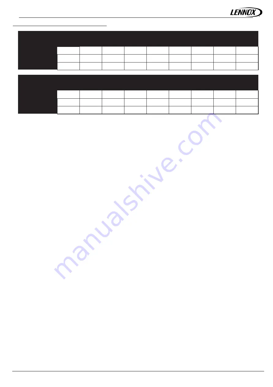
Correction tables for MRC and HYDROLEAN units:
Discharge gas velocity
Condensing temperature °C
correction factors
25
30
35
40
45
50
55
60
Suction
temperature °C
13
1,37
1,25
1,15
1,07
1,01
0,96
0,93
0,92
8
1,41
1,30
1,20
1,11
1,05
1,00
0,97
0,96
3
1,47
1,34
1,24
1,16
1,09
1,04
1,01
1,00
Liquid line velocity correction
Liquid line temperature °C, 5°C subcooled
factors
20
25
30
35
40
45
50
55
Suction
temperature °C
13
0,67
0,72
0,77
0,83
0,90
0,99
1,10
1,23
8
0,67
0,72
0,78
0,84
0,91
1,00
1,11
1,24
3
0,68
0,73
0,78
0,85
0,92
1,01
1,12
1,26
7.3.
Mechanical isolation of refrigerant lines
Isolate refrigerant lines from the building to prevent the vibrations normally generated by the lines to the building structure. Avoid bypassing
the isolation system on the unit by securing refrigerant lines or electrical conduits too tightly. Any vibrations will be transmitted to the building
by rigid piping.
Lack of vibration isolation on refrigerant pipework will lead to early failure of copper pipe and loss of gas.
7.4.
Pressure test
To avoid formation of copper oxide during brazing operations, blow a little dry nitrogen through the pipes.
Piping must be made with tubing that is perfectly clean, plugged during storage and between connections operations. During these
operations, observe the following precautions:
1. Do not work in a confined atmosphere, refrigerant fluid can cause asphyxiation. Make sure there is sufficient ventilation.
2. Do not use oxygen or acetylene instead of refrigerant fluid and nitrogen for leak testing: this could cause a violent explosion.
3. Always use a regulator valve, isolating valves and a pressure gauge to control test pressure in the system. Excessive pressure
can cause lines to burst damage to the unit and/or cause an explosion with severe personal injury.
Ensure conduct liquid line and gas line pressure tests are in conformity with applicable legislation. Before starting up a unit on a receiver,
the piping and the condenser must be dehydrated. Dehydration should be carried out using a double stage vacuum pump, capable of
drawing 600Pa absolute pressure vacuum.
Best results are obtained with a vacuum down to 100 Pa.
To get down to this level at normal temperatures, i.e. 15 °C, it is often necessary to leave the pump running for 10 to 20 hours. The duration
of pump operation is not a factor of efficiency. The pressure level must be checked before the unit is put into service.
7.5.
Refrigerant charge
Chillers with R410A must be filled in the liquid phase. Never charge a machine operating on R410a in the vapour phase (vapour): the
composition of the mixture could be modified. In liquid phase, connect either to a liquid isolating valve, or to the quick -connector on the
liquid line at the valve outlet.
In liquid phase, connect to a Schrader from the liquid line.
Note for all units:
Split units are supplied with a refrigerant or nitrogen holding charge. Before pulling down the vacuum for dehydration, completely purge
the unit. Every time refrigerant is added, check the state of the charge with the sight glass if provided and also by the amount of liquid sub
cooling at the condenser outlet according to the system design value. In all cases, do not top up the charge until the unit reaches a stable
state of operation. Don’t overcharge a system, this can adversely affect operation.
Overcharging causes:
• Excessive discharge pressure,
• A risk of damage for the compressor,
• Excessive power consumption.


