background image

24

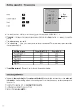
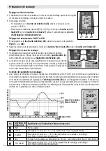
Welding parameters – Programming

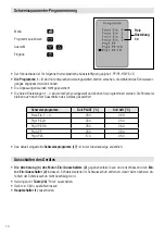
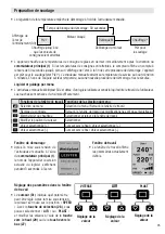
•   The hand extruder is suitable for the following types of thermoplastic: PP/PE-HD/PE-LD
•  

Programs 1 – 3 

include the relevant preset values, which can be adjusted during the course of the welding 

process.

•  The adjustments are not saved!
•   The free settings 1 - 4 are factory set and can be freely programmed. The parameters remain saved after 

the tool is switched off.

• The 

welding program (17)

 currently set is shown in the operating display.

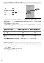
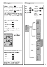
Free  

setting

1-4

Welding program 

Target PLAST [°C]

Target AIR [°C]

Free settings 1 – 4

230

260

Prg1 PE-LD

220 

260

Prg2 PE-HD

230

260

Prg3 PP 

230

260

Prg4 PVC

170

260

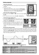
Menu 

Select program 

Scroll

Enter

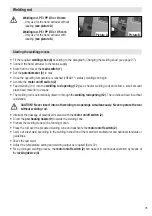
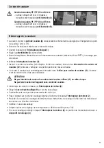
•   Release  the 

locking device (4) 

of the 

motor on/off switch (2)

 as applicable, and then let go of the 

motor on/

off switch (2

). Remove welding material in the welding shoe in order that the welding shoe is not damaged with 

the next start.

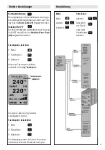
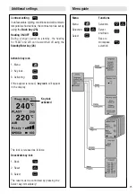
•  Switch off the heating with the 

Standby / Enter  key  (26).

•  Let the tool to cool down for approx. 5 min.
• Switch off at the 

main switch (1)

.

Switching off the tool

Содержание WELDPLAST S4

Страница 1: ...WELDPLAST S4 Leister Technologies AG Galileo Strasse 10 CH 6056 Kaegiswil Switzerland Tel 41 41 662 74 74 Fax 41 41 662 74 16 www leister com sales leister com D GB F E ...

Страница 2: ...2 Deutsch Bedienungsanleitung 3 English Operating Instructions 17 Français Instructions d utilisation 31 Espanõl Instrucciones de funcionamiento 45 D GB F E ...

Страница 3: ...ven Gasen Verbrennungsgefahr Blanke Metallteile und austretende Masse nicht in heissem Zustand berühren Gerät abkühlen lassen Heissluftstrahl und austretende Masse nicht auf Personen oder Tiere richten Gerät an eine Steckdose mit Schutzleiter anschliessen Jede Unterbrechung des Schutzleiters innerhalb oder ausserhalb des Gerätes ist gefährlich Nur Verlänge rungs kabel mit Schutzleiter verwenden Ne...

Страница 4: ...weltgerechten Wiederverwertung zuge führt werden Nur für EU Länder Werfen Sie Elektrogeräte nicht in den Hausmüll Spannung V 230 Leistung W 3680 Frequenz Hz 50 60 Luftmenge 20 C l min ca 400 mit Düse Nr 2 Seite 14 Luft Temperatur C max 350 Plastifizierte Temperatur C max 260 Schwingungspegel ah m s2 2 5 K 1 5m s2 Masse L B H mm ohne Schweissschuh 560 110 300 Gewicht kg ohne Netzanschlussleitung 8 ...

Страница 5: ...ogramm 18 Ist Wert Plast 19 Soll Wert Plast 20 Ist Wert Air 21 Soll Wert Air 22 Anzeigebalken 23 Ausstossanzeige 24 Menü Taste 25 Back Taste 26 Enter Taste 27 Down Taste 28 Select Taste 29 Up Taste 30 Statusanzeige 31 Cursor 9 Vorwärmdüse 10 Rohrklemme 11 Schutzrohr 12 Schweissdraht Einführung 13 Gerätegriff 14 Netzanschlussleitung 15 Handschutz 16 Heissluftgebläse 24 27 28 29 30 31 17 18 19 20 21...

Страница 6: ...smaschine mit dem Motor Ein Ausschalter 2 abzuschalten Den Hand Extruder mit entsprechend eingestelltem und fest ange zo ge nem Handgriff gemäss Abbildung auf eine stabile feuerfeste Unterlage stellen Durch Drehen des Kunststoffhandgriffes im Gegenuhrzeigersinn wird die Klemmung gelöst und durch Vor oder Zurückschieben kann der Griff in die ideale Arbeitsposition gebracht werden Zur Verwendung dur...

Страница 7: ...gabe schweissbereit Funktionen Arbeitsfenster Funktionen Menüauswahl Menüauswahl Menüauswahl Zurück zum Arbeitsfenster Kontrast einstellen Zurück zum Arbeitsfenster Änderung wird nicht gespeichert Heizung on off Selektieren und zurück zum Arbeitsfenster Cursorposition ändern Selektieren Selektierter Wert Cursor nach oben Selektierter Wert Selektierter Wert Cursor nach unten Selektierter Wert Start...

Страница 8: ...t der Ausstoss mit Ausstossanzeige 30 und Potentiometerstellung Minimum zu gross muss auf die nächstkleinere Schweissdrahtdicke gewechselt werden Überwachung der Schweissparameter Die Soll und Istwerte der Air Luft und PLAST Plastifizier Tem peraturen werden ständig überwacht Weicht ein Istwert vom entsprechenden Sollwert ab Wert ist ausserhalb des Toleranzbandes wird dies auf der Statusanzeige 30...

Страница 9: ...er Schweissdraht wird automatisch durch die Schweissdraht Einführung 12 eingezogen Drahtzuführung muss ohne Widerstand erfolgen ACHTUNG Niemals gleichzeitig in beide Schweissdraht Einführungen 12 Schweissdraht einführen Gerät nicht ohne Schweissdraht betreiben Masseförderung mit Motor Ein Ausschalter 2 unterbrechen Die Vorwärmdüse 9 auf die Schweisszone richten Mit pendelnden Bewegungen die Schwei...

Страница 10: ...gespeichert Das aktuell eingestellte Schweissprogramm 17 ist in der Arbeitsanzeige ersichtlich Freie Einstellung 1 4 Schweissprogramm Soll PLAST C Soll AIR C Freie Ein 1 4 230 260 Prg1 PE LD 220 260 Prg2 PE HD 230 260 Prg3 PP 230 260 Prg4 PVC 170 260 Menü Programm selektieren Auswahl Eingabe Die Arretierung 4 des Motor Ein Ausschalters 2 gegebenenfalls lösen und anschliessend den Mo tor Ein Aussch...

Страница 11: ...en Menü Menü Auswahl Selektieren Funktionen Auswahl Selektieren und Zurück zurück zum Arbeitsfenster Auswahl Tastensperre aktivieren 1 Menü 2 Tastensperre 3 Aktivieren Wurde die Tastensperre aktiviert erscheint im Display Tastensper Die Sperre kann wie folgt wieder zurückgestellt werden Tastensperre deaktivieren 1 Back 2 Rückstellen 3 Selektieren Die Bestätigung durch die Select Taste muss unmitte...

Страница 12: ...r Luft oder defekte Temperatursonde Err02 Übertemperatur der Kunststoffmasse oder defekte Temperatursonde Err04 Übertemperatur in der Motorenwicklung Motor ist überhitzt Err08 Übertemperatur des Heizelementes AIR oder Ausfall des Gebläsemotors Err10 Übertemperatur der Elektronik Err40 Kurzschluss der Temperatursonde Plast Es können auch mehrere Fehler gleichzeitig auftreten z B Err02 und Err04 Anz...

Страница 13: ... Schweissschuhhalter 34 mit Be fes tigungs schrauben 33 montieren Schweissschuh 8 und Schweissschuhhalter 34 müssen mit den Klemmschrauben 35 gut angezogen werden Verbrennungsgefahr Nur mit temperaturfesten Handschuhen arbeiten Der Schweissschuhwechsel muss am betriebswarmen Gerät vorgenommen werden Schweissschuhwechsel 8 Schweissschuh 32 Extrudierdüse 33 Befestigungsschraube 34 Schweissschuhhalte...

Страница 14: ...emperaturfesten Handschuhen arbeiten Zur Demontage der Heissluftführung 44 wird zuerst der Schweissschuh 8 entfernt Nach dem Lösen der gekonter ten Fixierschraube 45 an der Rohrklemme 10 und der Klemmschraube 47 am Heissluftführungs Verbinder kann die ganze Einheit abgezogen werden Montage in umgekehrter Reihenfolge Damit keine Vorwärmluft verloren geht ist bei erneuter Mon tage wiederum darauf zu...

Страница 15: ...lter 39 dient zum Aufsetzen der Schweissdrahtrolle ø 300mm Um eine optimale Drahtabwicklung zu gewährleisten ist der Schweissdraht durch die vorgesehene Öse 41 zu führen 37 39 38 41 40 Transportable Drahtabrollvorrichtung Die Vorrichtung ist für Schweissdrahtrollen mit Ø 300 mm ausgelegt Um eine optimale Drahtabwicklung zu gewährleisten ist der Schweissdraht durch die dafür vorgesehene Öse 41 zu f...

Страница 16: ...mehr an Wartung Netzanschlussleitung 14 und Stecker auf elektrische und mechanische Beschädigungen überprüfen Die Extrudierdüse 32 bei jedem Schweissschuhwechsel von Schweissgutrückständen befreien Schweiss schuhwechsel Seite 13 Service und Reparatur Gewährleistung Für dieses Gerät gelten die vom direkten Vertriebspartner Verkäufer gewährten Garantie oder Gewährleistungs rechte ab Kaufdatum Bei ei...

Страница 17: ...an cause burns Do not touch bare metal parts and emerging material while hot Allow the device to cool Do not direct stream of hot air or emerging material towards people or animals Connect device to power socket with protective earth conductor Any break in the protective earth conductor inside or outside the device is dangerous Only use extension cables with a protective earth conductor The nomina...

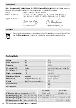
Страница 18: ... For EU countries only Do not dispose of electrical equipment with household refuse Voltage V 230 Power consumption W 3680 Frequency Hz 50 60 Air volume 20 C l min ca 400 with nozzle no 2 page 28 Air temperature C max 350 Plasticizing temperature C max 260 Vibration acceleration ah m s2 2 5 K 1 5m s2 Size L W H mm without welding shoe 560 110 300 Weight kg without power supply cord 8 7 Conformity ...

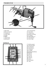
Страница 19: ...m 18 Actual value plast 19 Set value plast 20 Actual value air 21 Set value air 22 Bar display 23 Welding output display 24 Menu key 25 Back key 26 Enter key 27 Down key 28 Select key 29 Up key 30 Status display 31 Cursor 9 Pre heating nozzle 10 Tube clamp 11 Protective tube 12 Welding rod feeding 13 Tool handle 14 Power supply cord 15 Hand protection 16 Hot air blower 24 27 28 29 30 31 17 18 19 2...

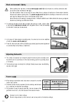
Страница 20: ... case of interruptions to welding work the drive motor can be switched off with the motor on off switch 2 Place the hand extruder with the handle appropriately positioned and tightened on a stable fireproof surface as illustrated The clamp is loosened by turning the plastic handle counter clockwise and the handle can be positioned in the ideal working position by sliding back or forwards The handl...

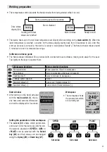
Страница 21: ...status display 30 Heating until ideal values are reached Motor release Ready to weld Workspace functions Menu selection functions Menu selection Menu selection Back to workspace Set contrast Back to workspace changes not saved Heating on off Select and back to workspace Change cursor position Select Selected value Cursor up Selected value Selected value Cursor down Selected value Start window Afte...

Страница 22: ...mum the next smallest welding rod thickness must be selected Monitoring the welding parameters The actual and ideal values of the AIR and PLAST temperatures are constantly monitored If an actual value deviates from the relevant ideal value value is outside the range of tolerance this will be indicated by a change in status on the status display 30 If necessary the drive motor will be temporarily d...

Страница 23: ...utomatically drawn in through the welding rod opening 12 The rod should feed in without resistance CAUTION Never insert into both welding rod openings simultaneously Never operate the tool without welding rod Interrupt the passage of plastizised material with the motor on off switch 2 Direct the pre heating nozzle 9 towards the welding zone Preheat the welding zone with a fanning motion Place the ...

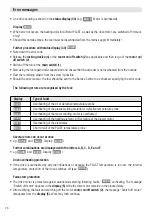
Страница 24: ...rrently set is shown in the operating display Free setting 1 4 Welding program Target PLAST C Target AIR C Free settings 1 4 230 260 Prg1 PE LD 220 260 Prg2 PE HD 230 260 Prg3 PP 230 260 Prg4 PVC 170 260 Menu Select program Scroll Enter Release the locking device 4 of the motor on off switch 2 as applicable and then let go of the motor on off switch 2 Remove welding material in the welding shoe in...

Страница 25: ...witched off using the Standby Enter key 26 Menu Menu Selection Select Functions Selection Select and Back Back to workspace selection Activate key lock 1 Menu 2 Key lock 3 Activating If the keypad is locked key lock will appear in the display The lock is released as follows Deactivate key lock 1 Back 2 Reset 3 Select The reset must be confirmed by pressing the Select key immediately Key lock activ...

Страница 26: ...f the air or defective temperature probe Err02 Overheating of the plastic welding material or defective temperature probe Err04 Overheating of the motor winding motor is overheated Err08 Overheating of the heating element AIR or failure of the blower motor Err10 Overheating of the electronics Err40 Short circuit of the PLAST temperature probe Several errors can occur at once e g Err02 and Err04 Di...

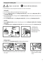
Страница 27: ...elding seam onto the welding shoe holder 34 with fastening screws 33 The welding shoe 8 and welding shoe holder 34 must be tightened properly with the clamp screws 35 Danger can cause burns Only work with heat resistant gloves The welding shoe must be changed while the device is still warm from operation Changing the welding shoe 8 Welding shoe 32 Extruder nozzle 33 Fastening screw 34 Welding shoe...

Страница 28: ... Replacing the pre heating nozzles Danger can cause burns Only work with heat resistant gloves To disassemble the hot air tube 44 firstly remove the wel ding shoe 8 After loosening the countersunk locating screw 45 on the tube clamp 10 and the clamping screw 47 on the hot air tube connector the complete unit can be removed Assembly in the reverse sequence Do ensure no pre heated air is lost when r...

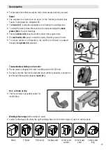
Страница 29: ...f welding rod ø 300 mm To ensure optimal rod dispensing the welding rod should be passed through the eyelets 41 provided 37 39 38 41 40 Transportable welding rod de reeler The de reeler is designed for rolls of welding rod with Ø 300 mm To ensure that the filler rod is unwound as smoothly as possible it should be fed through the specially designed eyes 41 41 Hot air tube on top The hot air tube is...

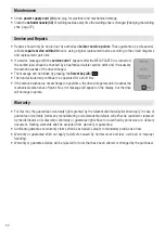
Страница 30: ...l no longer operate Maintenance Check power supply cord 14 and plug for electrical and mechanical damage Clean the extruder nozzle 32 of welding residue every time the welding shoe is changed Changing the welding shoe page 27 Service and Repairs Warranty For this tool the guarantee or warranty rights granted by the relevant distributor seller shall apply In case of guarantee or warranty claims any...

Страница 31: ...ure Ne touchez pas les pièces métalliques nues et la masse extrudée si ellessontchaudes Laissezrefroidirl appareil Nedirigezpaslejetd airchaudnilamasse extrudée sur les personnes ou les animaux Raccordez l appareil à une prise de courant équipée d un conducteur de protection Toute rupture du conducteur de protection à l intérieur ou à l extérieur de l appareil est dangereuse Utilisez exclusivement...

Страница 32: ...r les pays de l UE uniquement ne pas jeter les appareils électroniques avec les déchets ménagers Tension V 230 Puissance W 3680 Fréquence Hz 50 60 Débit d air 20 C l min ca 400 avec buse no 2 page 42 Température de l air C max 350 Température de plastification C max 260 Niveau vibration ah m s2 2 5 K 1 5m s2 Dimensions L I H mm sans patin de soudure 560 110 300 Poids kg Sans câble d alimentation s...

Страница 33: ...Valeur de consigne de l air 22 Diagramme d affichage 23 Affichage de débit 24 Touche de menu 25 Touche de retour 26 Touche d entrée de valeur 27 Touche de défilement de programme par le bas 28 Touche de sélection 29 Touche de défilement de programme par le haut 30 Affichage de l état de l entraînement 31 Curseur 9 Buse de préchauffage 10 Pince de tuyau 11 Tuyau de protection 12 Introduction du cor...

Страница 34: ...e arrêtée en actionnant l interrupteur du moteur 2 Il faut alors poser l extrudeuse à main avec la poignée réglée et fixée fer mement dans la position visible sur l illustration La surface où est posée la machine doit être stable et résistante au feu La pince de fixation se libère en tournant la poignée en matière synthétique dans le sens inverse des aiguilles d une montre La poignée peut alors êt...

Страница 35: ...tteintes Déblocage du moteur Prêt pour le soudage Fonctions de la fenêtre de travail Fonctions de la sélection du menu Sélection du menu Sélection du menu Retour à la fenêtre de travail Réglage du contraste Retour à la fenêtre de travail les modifications ne sont pas enregistrées Marche arrêt du chauffage Sélectionner et retour à la fenêtre de travail Modifier la position du curseur Sélectionner V...

Страница 36: ...ectement inférieure Contrôle des paramètres de soudage Les valeurs de consigne et valeurs réelles des températures AIR et PLAST sont contrôlées en permanence La déviation d une valeur réelle par rapport à la valeur de consigne correspondante la valeur se situe en dehors de la bande de tolérance est signalée sur l affichage de l état 30 par un changement de statut Si nécessaire le moteur d entraîne...

Страница 37: ...etite quantité de masse extrudée Le cordon le soudure sera automatiquement introduit dans l orifice pour cordon de soudure 12 L avance ment du cordon doit se faire sans résistance ATTENTION Ne pas introduire du cordon de soudure dans les deux orifices 12 en même temps Ne pas faire fonctionner l appareil sans cordon de soudure Interrompre la sortie de la masse par l interrupteur du moteur 2 Diriger...

Страница 38: ...ectionné est affiché en temps réel dans l affichage de travail Réglage à choix libre 1 4 Programme de soudage Valeur de consigne PLAST C Valeur de consigne AIR C Réglages à choix libre 1 4 230 260 Prg1 PE LD 220 260 Prg2 PE HD 230 260 Prg3 PP 230 260 Prg4 PVC 170 260 Menu Sélection du programme Choix Entrée Débloquer le dispositif de blocage 4 par une brève pression sur l interrupteur du moteur 2 ...

Страница 39: ... Fonctions Sélection Sélectionner et Retour Retour à la fenêtre de travail sélection Activer le verrouillage des touches 1 Menu 2 Verrouillage des touches 3 Activer Si le verrouillage des touches a été activé verrouillage des touches s affiche sur l écran Le verrouillage peut être réinitialisé comme suit Désactiver le verrouillage des touches 1 Retour 2 Retour 3 Sélectionner La confirmation par le...

Страница 40: ...éfectueuse Err02 Surchauffe de la masse synthétique ou sonde de température Err04 Surchauffe du bobinage du moteur moteur en surchauffe Err08 Surchauffe des éléments chauffants AIR ou arrêt du moteur de la soufflante Err10 Surchauffe de l électronique Err40 Court circuit de la sonde de température PLAST Des messages d avertissement peuvent aussi signaler simultanément plusieurs problèmes Par ex Er...

Страница 41: ...le patin de soudage 8 en desserrant les vis de fixation 33 du support du patin de soudage 34 Montage Montez un patin de soudage 8 adapté au cordon de soudure sur le support du patin de soudage 34 à l aide des vis de fixation 33 Le patin de soudage 8 et son support 34 doivent être correctement fixés au moyen des vis de blocage 35 Remplacement du patin de soudage 8 Patin de soudage 32 Buse d extrusi...

Страница 42: ...sistants aux écarts de température Pour démonter le tuyau d air chaud 44 il faut tout d abord retirer le patin de soudure 8 Après avoir desserer la vis de fixation 45 bloquée par un écrou sur la bride du tuyau 10 et desserrer la vis de la bride 47 sur le raccord du tuyau d air chaud 44 toute la pièce peut être retirée Le remontage se fait en suivant ces étapes en sens inverse Afin d éviter toute p...

Страница 43: ...e Ø 300 mm Le cordon de soudure doit traverser la boucle 41 prévue à cet effet pour garantir son déroulement optimal 37 39 38 41 40 Dispositif transportable de déroulement du cordon de soudure Le dispositif est conçu pour bobines de cordons de soudure de Ø 300 mm Afin de garantir un déroulement optimal du cordon de soudure ce dernier doit être inséré dans les œillets 41 prévus 41 Conduite d air ch...

Страница 44: ...ation secteur 14 et la fiche à la recherche de dommages électriques et mécaniques Eliminez les résidus de matière de soudure au niveau de la buse d extrusion 32 à chaque remplacement du patin de soudage remplacement du patin de soudage voir p 41 Service et réparations Garantie légale Les droits de garantie fabricant et de garantie légale accordés par le partenaire commercial ou vendeur direct s ap...

Страница 45: ...emaduras No toque las piezas metálicas desnudas ni el material de salida en estado caliente Deje enfriar el aparato No dirija el chorro de aire caliente ni el material de salida a personas o animales Conecte el aparato a una base con toma de tierra Es peligroso trabajar sin toma de tierra Puesta a tierra tanto dentro como fuera del aparato son peligrosas Utilice únicamente cables alargadores con t...

Страница 46: ...medio ambiente Solo para países de la Unión Europea No desechar jamás equipos eléctricos en la basura doméstica Tensión V 230 Potencia W 3680 Frecuencia Hz 50 60 Volumen de aire 20 C l min 400 Clase de protección I página 56 Temperatura del aire C max 350 Temperatura de plastificado C max 260 Nivel de oscilación ah m s2 2 5 K 1 5m s2 Medidas L An Al mm sin zapata de soldadura 560 110 300 Peso kg s...

Страница 47: ...mperatura programada 20 Temperatura real del aire 21 Temperatura prgramada 22 Barra indicadora 23 Indicación del rendimiento 24 Tecla Menú 25 Tecla Atrás 26 Tecla Enter 27 Tecla Abajo 28 Tecla Seleccionar 29 Tecla Arriba 30 Indicación de estado 31 Cursor 9 Tobera de precalentamiento 10 Abrazadera de tubo 11 Tubo de protección 12 Entrada de varilla para soldar 13 Empuñadura del aparato 14 Cable de ...

Страница 48: ...de accionamiento por medio del interruptor de encendido apagado del motor 2 Coloque la extrusora manual con el mango debidamente ajustado y apretado en una base refractaria según lo indicado en la imagen Si gira el mango de plástico en sentido contrario a las agujas del reloj éste se desbloquea y puede ajustarlo hacia adelante o atrás hasta encontrar la posición de trabajo ideal Además el mango pu...

Страница 49: ...ración del motor Preparado para la soldadura Funciones en la ventana de trabajo Funciones en el menú de selección Menú de selección Menú de selección Volver a la ventana de trabajo Ajustar contraste Volver a la ventana de trabajo no se guardará el cambio Calefacción ON OFF Seleccionar y volver a la ventana de trabajo Modificar posición del cursor Seleccionar Valor seleccionado Cursor hacia arriba ...

Страница 50: ...ás fino que le siga Control de los parámetros de soldadura Los valores teóricos y reales de las temperaturas AIR y PLAST se controlan constantemente Si un valor real es diferente al valor teórico correspondiente valor fuera del rango de tolerancia se señalizará en el indicador de estado 30 mediante un cambio de estado Si es necesario se bloqueará el motor de accionamiento de forma provisional hast...

Страница 51: ... pasará automáticamente a través del orificio de la varilla 12 La alimentación de varilla debe efectuarse sin resistencia ATENCIÓN Nunca introduzca varilla para soldar simultáneamente en los dos orificios de la varilla 12 No debe utilizarse el aparato sin varilla para soldar Interrumpa la expulsión de material con el interruptor de conexión desconexión del motor 2 Dirija la tobera de precalentamie...

Страница 52: ...e el programa de soldadura 17 actualmente elegido Ajuste libre 1 4 Programa de soldadura Consigna PLAST C Consigna AIR C Ajuste libre 1 4 230 260 Prg1 PE LD 220 260 Prg2 PE HD 230 260 Prg3 PP 230 260 Prg4 PVC 170 260 Menú Seleccionar programa Selección Introducción Desbloquee el bloqueo 4 del interruptor de conexión desconexión del motor 2 cuando sea necesario y luego suelte el interruptor de cone...

Страница 53: ...a Standby Enter 26 Menú Menú Selección Seleccionar Funciones Selección Seleccionar y volver Volver a la selección de la ventana de trabajo Activar bloqueo de teclas 1 Menú 2 Bloqueo de teclas 3 Activar Si se activa el bloqueo de teclas en la pantalla aparece Bloqueo de teclas El bloqueo se puede cancelar de la siguiente forma Desactivar bloqueo de teclas 1 Back 2 Restablecer 3 Seleccionar La tecla...

Страница 54: ...temperatura del material termoplástico o sonda de temperatura defectuosa Err04 Sobretemperatura en la bobina del motor motor sobrecalentado Err08 Sobretemperatura del elemento calentador AIR o parada del motor del ventilador Err10 Sobretemperatura de las partes electrónicas Err40 Cortocircuito de la sonda de temperatura Plast Pueden producirse varios errores simultáneamente p ej Err02 y Err04 indi...

Страница 55: ...ta 34 con los tornillos de sujeción 33 La zapata de soldadura 8 y el soporte de zapata 34 deben estar bien sujetos con tornillos de fijación 35 Peligro de quema duras Trabajar sólo con guantes de protección tér mica El cambio de la zapata de soldadura se debe realizar con el dispositivo aún caliente Cambio de la zapata de soldadura 8 Zapata de soldadura 32 Boquilla de extrusión 33 Tornillos de suj...

Страница 56: ...as Trabajar sólo con guantes de protección térmica Para desmontar la guía de aire caliente 44 retire pri mero la zapata de soldadura 8 Después de soltar las contratuercas de fijación 45 de la abrazadera del tubo 10 y del perno de apriete 47 en la conexión de la guía de aire caliente retire toda la unidad Para el montaje siga el mismo proceso en el orden inverso Para no desperdiciar aire caliente c...

Страница 57: ...pase la varilla para soldar a través del ojo 41 previsto 37 39 38 41 40 Dispositivo portátil de desbobinado de alambre El dispositivo está diseñado para rollos de alambre de soldadura con Ø 300 mm Para garantizar un desbobinado correcto del alambre se debe guiar el alambre de soldadura a través del ojal 41 previsto 41 Guía de aire caliente por arriba La guía de aire caliente por arriba es idónea p...

Страница 58: ...ar Mantenimiento Controlar que el cable de conexión de red 14 y el enchufe no tengan daños mecánicos ni eléctricos Retirar los restos de soldadura de la boquilla de extrusión 32 en cada cambio de zapata de soldadura Cambio de la zapata de soldadura véase pág 55 Servicio y reparaciones Garantía Para este dispositivo tienen validez los derechos de garantía comercial o legal concedidos por el socio d...

Страница 59: ......
Страница 60: ...2018 Art 118 739 part 1 Your authorised Service Centre is Leister Technologies AG Galileo Strasse 10 CH 6056 Kaegiswil Switzerland Tel 41 41 662 74 74 Fax 41 41 662 74 16 www leister com sales leister com Copyright by Leister ...

Отзывы: