background image

35

Leica ST5020

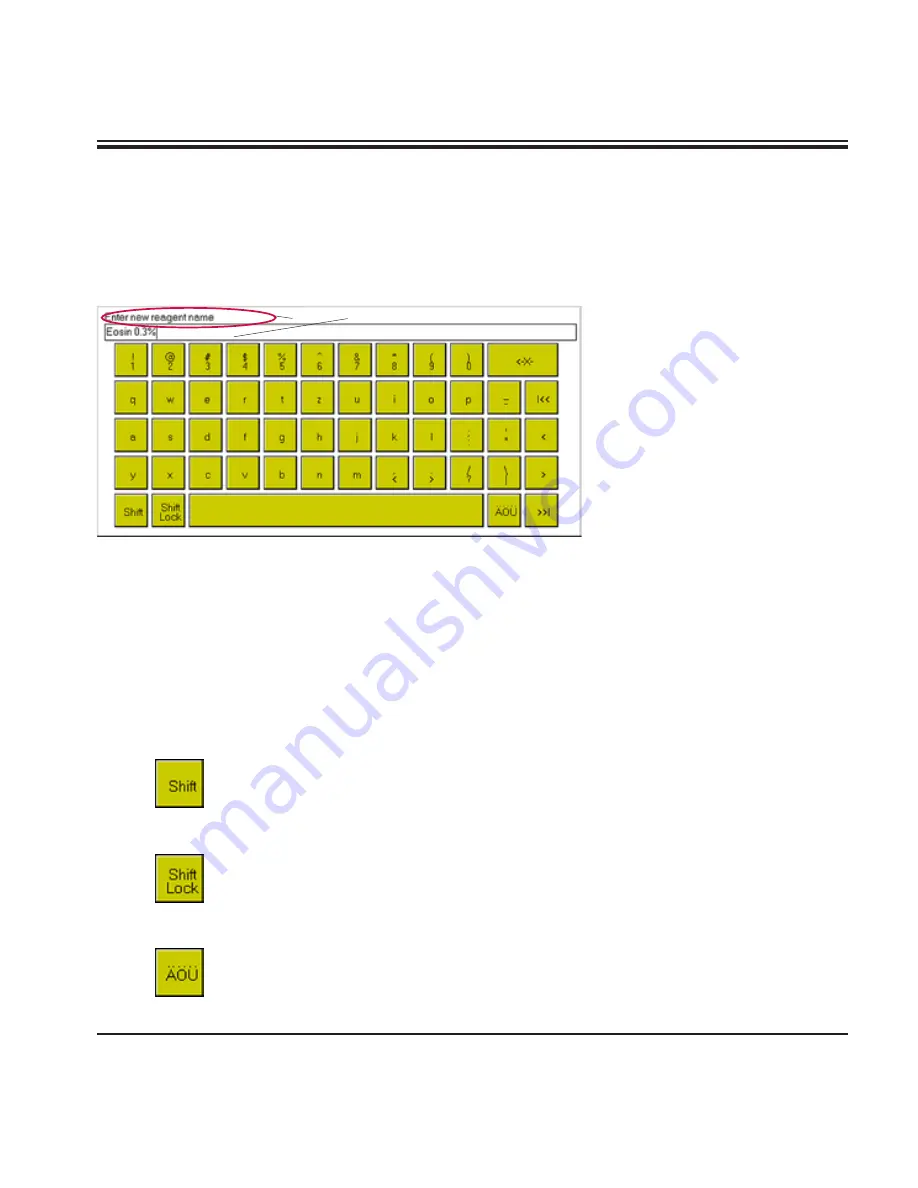
The alphanumeric keyboard 

(

Fig. 29

) resembles a computer 

keyboard. An entry field (

5

) and 

instructions on what kind of data 

to enter (

4

) are located above the 

keyboard. The amount of charac-

ters that can be entered varies, 

depending on the type of data to 

be entered. If there is a predeter-

mined number of characters to 

be entered, that number will be 

displayed in the entry field. The 

cursor is located on the left.

Alphanumeric keyboard

4

5

Fig. 29

The maximum number of characters to be entered may not be exceeded. 

The following numbers are predefined:
Reagent names: 

maximum 20 characters

Program names: 

maximum 20 characters

Program abbreviation:  maximum 3 characters

Passwords:   

minimum 4 characters, maximum 20 characters.

The following buttons have special functions:

If pressed, button remains locked, all letters will be displayed in capitals.  

After any button has been pressed, 

SHIFT 

is released and the keyboard 

will return to small letters.

If pressed, button remains locked - all letters will be written in capitals. 

Press 

SHIFT LOCK

 once more to return to small letters.

Press this button to display special characters, above all vowels carrying 

accents. These can also be displayed in capitals by pressing 

SHIFT

/

SHIFT 

LOCK

. After a special character has been selected, the keyboard auto-

matically reverts to standard indication. 

5.3.2 Data entry

Parameters and data can be set / entered several different ways: 

5.   Operation

Содержание ST5020

Страница 1: ...tions for Use Leica ST5020 Multistainer Leica ST5020 V2 0 RevG English 07 2016 Order No 14 0475 80101 RevG Always keep these instructions near the instrument Read carefully before working with the ins...

Страница 2: ......

Страница 3: ...f the present manual are not to be considered as warranted characteristics of our products These are determined only by the contract pro visions agreed between ourselves and our cus tomers Leica reser...

Страница 4: ...17 4 Setting up the instrument 18 4 1 Installation site requirements 18 4 2 Installing the instrument 18 4 3 Tap water supply connection 19 4 4 Installing the oven optional 22 4 5 Connecting the air e...

Страница 5: ...61 5 6 2 Defining the program steps 62 5 6 3 Assigning a clip color 67 5 7 Programs in process 69 5 8 Staining 70 5 8 1 Loading the racks 70 5 8 2 Starting programs 71 5 8 3 Interrupting a staining p...

Страница 6: ...on CSA the National Sanitation Founda tion International NSF and others In vitro diagnostics IVD medical de vice Observe the Instructions for Use Environmental protection symbol of the China RoHS dire...

Страница 7: ...instructions contained in this manual Any other use of the instrument is considered improper The instrument may be operated only ac cording to the instructions contained in this manual Any other use o...

Страница 8: ...refer to the CE declaration of conformity on our Inter net site www LeicaBiosystems com 2 1 Safety instructions This Instructions for Use includes important in formation related to the operating safet...

Страница 9: ...ent will automatically adjust to the required voltage and frequency at the place of installation If new ovens are installed they must be adjusted to the voltage and frequency required at the installat...

Страница 10: ...the instrument off and disconnect mains power Do not clean the instrument with solvents containing acetone or xylene No liquid may be spilled into the internal components of the instrument neither dur...

Страница 11: ...mponents and specifications Fig 1 Activated carbon filter Transfer arm Lid Wash stations Single Double carrier Reagent container Color touch screen Mains switch Slot for PCMCIA card Load drawer Exit d...

Страница 12: ...for Oven Modules Secondary fuses Oven Modules Transfer to Coverslipper optional Drain hose Exhaust air duct Drain outlet Water inlet Stations 8 12 DI Water inlet Station 7 Fan electronic Data connecti...

Страница 13: ...ly valve controlled CodeRackTM Programmable Slide Rack for automatic rack start Overflow Protector sensor in stainless steel sink Integrated fume control system with external hose filter Optional Acce...

Страница 14: ...3 4 connection for water tap 14 0475 32325 1 V strainer 3 4 40 22 A6 strainer for inlet hose 14 0456 36101 1 Threaded nippel 14 0474 33063 2 Gaskets for tap water inlet hose 14 0300 00132 1 Box level...

Страница 15: ...lation category II 800 V impulse 120 V systems 1500 V impulse 240 V systems Remote alarm relay 24 V AC DC maximum 2 A Connection potential free contact can be operated both as normally open and as nor...

Страница 16: ...0 specimen slides Total number of stations 40 36 4 Oven Total number of reagent stations max 34 Reagent container volume 450 ml Number of wash stations max 5 and 1 DI water optional Oven optional 2 or...

Страница 17: ...ime in these sta tions Wash stations The wash system consists of five optional six wash stations each ca pable of holding one slide rack Water enters the wash station through a connection piece 2 in t...

Страница 18: ...rument lid without any problem Virtually vibration free floor Stable ambient temperature between 10 C and 40 C Relative air humidity of maximum 80 non condensing Do not place near instruments which mi...

Страница 19: ...7 7 4 Setting up the instrument Water filter In addition to the filter sieve supplied item 3 in Fig 6 Leica recom mends installing a sediment filter between the water extraction outlet and ST5020 to g...

Страница 20: ...e other end into inlet 8 in Fig 7 If station no 7 Fig 3 will also be used as a tap water station connect a second tap water inlet hose optional accessory to in let 9 Inlet 9 only provides water or any...

Страница 21: ...wards and retighten screw 11 Turn screw 15 to the left use screwdriver until hose clamp 14 opens wide enough to be slid over waste water hose 13 Fit waste water hose 13 onto outlet con nection piece 1...

Страница 22: ...verify whether it is complete 15 16 17 18 19 22 21 20 Fig 10 Check the voltage selector setting and ad just if necessary Important The voltage selector switch must be set to the same mains voltage as...

Страница 23: ...remove cover panel 26 Store screws and cover panel in safe place for further use Remove cover panel 28 located to the right of the electrical connections at the rear wall of the instrument To remove p...

Страница 24: ...rument for that purpose If a second oven has been ordered install it the same way as the first Fasten cover item 17 Fig 10 so that the voltage range selected for the oven 15 is the same as the engrave...

Страница 25: ...e 64 see Fig 18 right Tighten screw 67 of hose clamp 62 turn to the right to secure the hose 68 66 66 Fig 18 64 63 67 62 65 4 Setting up the instrument If the instrument is operated without activated...

Страница 26: ...all of the filter housing 34 Fig 19 33 34 35 Fig 18 Filter inserted 51 4 Setting up the instrument 4 7 Leveling the instrument Once all accessories are installed don t forget the rear panel move the i...

Страница 27: ...ition by screwing the adjustable feet in out as needed For leveling position box lev el 38 alternately in positions A and B see Fig 22 on the vessel holder frame Screw the instrument feet inward outwa...

Страница 28: ...45 Data connections Printer port 47 A suitable printer and cable can be recom mended by your Leica distributor If conform ance to electromagnetic interference stand ards is essential a specially shiel...

Страница 29: ...evice is connected to the printer via a 6 3 mm diameter jack connector optional accessory For details on how to connect a remote alarm device to the Leica IP please contact your lo cal Leica sales off...

Страница 30: ...ecommended that the Leica ST5020 be plugged into a wall socket that has Ground Fault Circuit Interruption GFCI protection as an additional electrical safeguard Before you connect the instrument to the...

Страница 31: ...nsfer arm Create the PROGRAMS needed Existing programs can be copied and modified Open the REAGENT LIST menu check the settings and complete if necessary Verify whether DATE and TIME are correctly set...

Страница 32: ...n the screen The number of accessible control elements depends on the access level selected Status bar Operation Button bar Current date Current time Access level selected Fig 26 Online help on curren...

Страница 33: ...h time the button is pressed the next parameter is accessed start ing again with the first after the last one in the row has been selected Disabled Enabled Button symbols The six buttons described bel...

Страница 34: ...e displayed starting with the first row ending with the last row of the table with the highlighting bar jumping to the first content row on the page Each table contains a PRINT button If the button is...

Страница 35: ...maximum 20 characters Program abbreviation maximum 3 characters Passwords minimum 4 characters maximum 20 characters The following buttons have special functions If pressed button remains locked all l...

Страница 36: ...the cursor is deleted Fig 30 Entry field located above the numeric keypad left aligned Instructions on which parameter to be en tered 6 are displayed above the entry field Entry position is marked by...

Страница 37: ...ssword has been allocated the keyboard will appear on the screen See chapter 5 4 3 for details on password allocation Enter the Admin password and confirm The SUPERVISOR symbol will then be dis played...

Страница 38: ...ng the instrument on the main menu will be displayed only if the language is changed INSTRUMENT STATUS is actually the standard screen In all functional descriptions below INSTRUMENT STATUS is assumed...

Страница 39: ...and allocate Set user defined system parameters Calibrate screen Determine speed and number of dips Define screen displays and printouts Set control date and time determine the station type and alloc...

Страница 40: ...to the alternative measuring unit Language selection To select between the two languages that are available one of these two languages always being English The second language default German next to...

Страница 41: ...s 3 and 4 can be set The level currently selected is indicated on the button TEST The alarm type set sound intensity will sound for approx 10 secs 5 4 2 Alarm All of the settings for the menus STATION...

Страница 42: ...o load station After rack has been removed or program allocated Alarm 1 Rack bearing an unknown clip placed into load station After rack has been removed or color allocated to unknown clip Alarm 3 Pau...

Страница 43: ...be switched from yes to no and vice versa Switching password verification on off Changing the supervisor password To change the password the currently valid password must be en tered first Press ENTE...

Страница 44: ...using the arrow buttons After having set the date press CONFIRM to exit To set the time press TIME the TIME window opens up Use the arrow buttons to set HOURS and MINUTES As soon as you press CONFIRM...

Страница 45: ...f the corresponding program No dips are performed if the setting Number of Dips 0 is used even if Yes is entered in the DIP column in the program Fig 40 5 Operation DIP AMPLITUDE Defines the stroke le...

Страница 46: ...ocols will be printed at what time Daily printout can be switched OFF and ON for each protocol press the corresponding yes no button If OFF is selected for all printable protocols no daily printout wi...

Страница 47: ...agents that are not used The Reagent Management System RMS can be switched on off in this menu Press NEW the keyboard opens up Enter the name of the new reagent and confirm Up to 20 characters per rea...

Страница 48: ...sed Maximum number of racks that can be pro cessed until the next reagent change In instrument status a red bar in the station button indicates how long a reagent has already been used de pending on t...

Страница 49: ...Last change Date when the reagent was last changed Racks Number of racks that have been processed in a particular sta tion since the reagent was last changed Racks max Maximum number of racks that sho...

Страница 50: ...press CANCEL 5 Operation 5 4 8 Station options Screen indication and func tionality of stations are iden tical to the INSTRUMENT STATUS screen see Fig 49 Pressing a station button opens up the STATION...

Страница 51: ...reen response to buttons being pressed We recommend to use a pen for the calibration procedure 3 2 1 Standard appearance Button pressed The pen must be placed exactly on the red dot 1 The dot will mov...

Страница 52: ...am details All saved clips code and color allocation The error log Errorlog txt Fig 48 This menu allows all instrument data to be written to a PCMCIA card It is even possible to load saved data from s...

Страница 53: ...menu by mistake or there is no empty PCMCIA card available do NOT insert the card into the slot and press the BACKUP button to leave the data backup screen No data will be written and the text Backup...

Страница 54: ...he colored program buttons 1 is pressed the PROGRAM MING menu of the corresponding program opens up See chapter 5 6 for details The SCHEDULE button leads to the Schedule menu where all racks currently...

Страница 55: ...the button a bar 4 may be displayed providing different types of information depending on the type of station The second and third line are activated when a station is used in a program run The first...

Страница 56: ...een exceed ed the bar blinks in two second intervals Assigning the reagent Select a reagent station via the corresponding button and press the REAGENT LIST button in the STATION DETAILS menu Fig 51 Se...

Страница 57: ...nding on the station type chosen ad ditional station information is displayed Information displayed for all station types 9 station number station type rack number Rack number only if a rack is in the...

Страница 58: ...Racks max Number of racks as per RMS that can still be pro cessed before the reagent needs to be changed Even when the RMS is switched off an internal log is kept in the instrument Therefore all data...

Страница 59: ...respectively have been converted into reagent stations The same in reverse order applies for converting stations back into load unload stations Press CHANGE STATION TYPE 5 to access the STATION TYPE...

Страница 60: ...lumn headers CLIP COLOR ABBR and PROGRAM NAME are displayed as buttons In addition the buttons DETAILS COPY DELETE and NEW are displayed i e programs can be edited in this screen Individual button fun...

Страница 61: ...ode and will be displayed as pressed wider border Fig 56 Existing color allocations may be changed at any time For that pur pose go to the program list see Fig 55 for further details and high light th...

Страница 62: ...ist of the individual program steps is completely empty The number in the STEP column indicates the order in which the sta tions will be used Press INSERT ROW a new program row step is created in the...

Страница 63: ...play switches to the PROGRAMMING menu Fig 60 Pressing RMS gives you access to the RMS protocol Fig 59 a table providing informa tion on the current configuration which rea gent in which station See al...

Страница 64: ...t ready to be started Assign the reagent selected for the step to the correct station in INSTRUMENT STATUS see chapter 5 5 2 This is required to ensure that the correct reagent is in the station since...

Страница 65: ...program Press EXACT to alter between yes exact and no not exact Immersion times at exact steps are achieved to within 1 second Immersion time at non exact steps is at least as long as defined most of...

Страница 66: ...fferent types of last steps can be defined 1 Last step unload station Go to CHOOSE STATION and select EXIT as last station 2 Last step transfer station to Cover Slipper optional Go to CHOOSE STATION a...

Страница 67: ...If the clip color white is selected the instrument will switch to MANUAL PROGRAM START where any program can be selected and started see chapter 5 8 2 5 6 3 Assigning a clip color Fig 63 Every time t...

Страница 68: ...ion procedure As the color white has been selected the instrument switches auto matically to MANUAL PROGRAM START where you can allocate the desired program to the rack which is now equipped with a wh...

Страница 69: ...t yes no Provides information on wheth er a step has been defined as exact or non exact Fig 65 Remaining station time Shows the remaining immersion time of the rack in the station Total remaining proc...

Страница 70: ...the racks as shown in Fig 66 in one of the load sta tions with the clips facing outwards to wards the user Each rack must bear a clip corresponding to the program to be run Close the drawer completel...

Страница 71: ...rder of optimized throughput not nec essarily in the order in which they have been placed into the load station Loading a clip not allocated to a program any longer If a rack placed into the load stat...

Страница 72: ...o be allocated See chapter 5 6 3 Caution bear in mind any steps defined as exact During the color allocation procedure the instrument is paused The programs in progress are paused until the color allo...

Страница 73: ...lts might be negatively affected The duration of the step will be extended by the duration of the pause If PAUSE buttun has been pressd druring an exact step is in process a warnig message will be app...

Страница 74: ...4 Finishing programs Unloading racks from the unload drawer If a rack is located in the unload drawer the alarm type 1 sounds The code of the completed program and in the bottom row the basket number...

Страница 75: ...d confirm that the rack has been removed Press CONFIRM the current staining run is aborted and removed from the list of pending runs Staining will be resumed starting with the next rack If the program...

Страница 76: ...rument alcohol detergents containing alcohol window cleaner abrasive cleaning powders solvents containing acetone or xylene No liquid may come into contact with the electrical connections or spill int...

Страница 77: ...y however not be exposed to this solution for a lengthy period of time e g overnight Therefore rinse with abundant water after cleaning with sodium hypochlorite Slide racks Clean with household or lab...

Страница 78: ...e 16 for further details Remove and clean the reagent vessels A dishwasher up to 65 C can be used Check waste water hose for accumulated dirt and clean if necessary Remove paraffin residues from paraf...

Страница 79: ...the error log for error messages access the error log either view in menu VIEW PRINT ERROR LOG or print it out entries are listed in chronological order 7 2 1 Excessively high water level in the drai...

Страница 80: ...ecessary Depending on the relevant staining steps at the time of the alarm the user must secure the specimen so that no damage to the specimen results for example by transferring them into suitable co...

Страница 81: ...pecimen so that no damage to the specimen results for example by transferring them into suitable compatible reagents Programs already started and assigned to the manually removed spec imen slide holde...

Страница 82: ...rument malfunctions failures are caused by defective fuses 7 3 Power failure 7 Troubleshooting Malfunction failure Instrument not working no response No data can be entered via touch screen or touch s...

Страница 83: ...fuse holder in the example above F1 T2A To replace the fuse in fuse holder F1 select the replacement fuse marked 2A see Fig 69 Only the fuse marked 2A can be inserted into fuse holder F1 The same appl...

Страница 84: ...time The fuse holder is released and can be re moved 2 3 Remove the defective fuse 3 from the fuse holder 2 and insert the correct type re placement fuse Reinsert the fuse holder together with the fu...

Страница 85: ...ion or the or ganization from which you have purchased the contractual product shall apply exclusively Technical service information If you require technical service or replacement parts please contac...

Страница 86: ...Water Station 12 Water Station 13 Reagent Station 14 Reagent Station 15 Reagent Station 16 Reagent Station 17 Reagent Station 18 Reagent Station 19 Reagent Station 20 Reagent Station 21 Reagent Statio...

Страница 87: ...on 12 Water Station 13 Reagent Station 14 Reagent Station 15 Reagent Station 16 Reagent Station 17 Reagent Station 18 Reagent Station 19 Reagent Station 20 Reagent Station 21 Reagent Station 22 Reagen...

Страница 88: ...34525 Lid for 12 vessels assy 14 0475 33644 Adapter Sakura 14 0475 34515 Adapter Medite 20 14 0475 34516 Adapter Medite 30 14 0475 34517 Adapter Shandon 14 0475 34518 Adapter Microm 30 14 0475 34943...

Страница 89: ...TS5025 Transfer station assy ST5020 CV5030 14 0478 36703 Demo Box Leica ST5020 14 0475 36230 Activated carbon filter 14 0474 32273 Base plate ST5020 CV5030 14 0475 37647 Leica ST Ultra Clearing Agent...

Страница 90: ...90 Instructions for Use V2 0 RevG 07 2016 Notes...

Страница 91: ......

Страница 92: ...www LeicaBiosystems com Leica Biosystems Nussloch GmbH Heidelberger Stra e 17 19 D 69226 Nussloch Phone 49 6224 143 0 Fax 49 6224 143 268 Internet www LeicaBiosystems com...

Отзывы: