background image

5

1. Safety instructions

Prior to the operation of the Leica EM KMR2 read the instruction manual carefully.
Always use safety goggles during operation to avoid eye injury.
Clean the instrument regularly with a brush to remove glass splinters.
Store broken knives safely in the knife boxes provided.
Do not leave knives laying around or on the Leica EM KMR 2.
Used knives should be put into a marked “sharps” box for safe disposal.

Symbols in this manual and their meaning

Warning:
take extra care.

Notes:
Important information for the user.

Содержание EM KMR2

Страница 1: ...1 Leica EM KMR2 Leica EM KMR2 Leica EM KMR2 Leica EM KMR2 Leica EM KMR2 Operating Manual Operating Manual Operating Manual Operating Manual Operating Manual Order Number 177032 Leica EM KMR2 GA E 06 03 ...

Страница 2: ...2 ...

Страница 3: ... 3 2 Packing list 3 3 Installation 4 Description of the LEICA EM KMR2 5 Knifemaking 5 1 Hints 5 2 Making squares 5 3 Making knives from a square 5 4 Evaluation of the knife edge 6 Customised adjustments 6 1 Knife shoulder fine adjustment 7 Care and maintainance 7 1 Replacement of the scoring wheel 7 2 Adjusting the scoring pressure 8 Mounting troughs Trufs onto the knife 9 Accessories and consumab...

Страница 4: ...4 ...

Страница 5: ...njury Clean the instrument regularly with a brush to remove glass splinters Store broken knives safely in the knife boxes provided Do not leave knives laying around or on the Leica EM KMR 2 Used knives should be put into a marked sharps box for safe disposal Symbols in this manual and their meaning Warning take extra care Notes Important information for the user ...

Страница 6: ...6 Fig 1 Fig 2 Breaking pins Fig 3 Knife edge Counterpiece Knife shoulder Counterpiece Knife shoulder Knife edge Fig 3a ...

Страница 7: ...nd the counterpiece knife shoulder is small when the fracture occurs close to the corner The short score was suggested for cryo knives as the free break is longer resulting in the sharpest longest useable knife edge Griffiths et al 1983 Tokuyasu 1986 Each score is preset and equidistant from the corners of the square During the break the glass sits on two breaking pins and is also held from above ...

Страница 8: ...8 Fig 4 Scoring angle Real knife angle Fig 5 Stress line ...

Страница 9: ...5 when the knife shoulder is smaller then 0 2mm Increasing the height of the knife shoulder 0 2mm results in an even larger knife angle which can be over 55 Fig 4 2 4 Length of useful edge When a glass knife edge is examined under darkfield illumination using a stereo microscope or on LEICA Ultramicrotomes using the back light chapter 5 4 it can be seen that the central part is most useful for ult...

Страница 10: ...10 Fig 6 Fig 7 Fig 8 Side view Fig 8 ...

Страница 11: ...ing head Fig 8 Check all items against the packing list and examine each item for transport damage 3 2 Packing list LEICA EM KMR2 Box glass strips 6 4 x 400 x 25mm dust cover and Allen key no picture 30 strips Knife handling fork 1pc Spare scoring wheel cartridge 1pc Knife box 3pcs Pair of knives produced with this LEICA KMR2 3 3 Installation Place the Leica EM KMR2 on a sturdy laboratory bench or...

Страница 12: ...12 Fig 9 1 2 3 4 5 6 7 8 9 10 11 ...

Страница 13: ... back 5 Ruler acts generally as a stop for the glass strip The glass strip is pressed against the ruler before it is clamped The left hand ruler acts also as a track for the moveable stop with its four click stop positions 6 Scoring mark selector can be set by rotating to two different scoring lengths The long score 22 mm is for scoring the glass strips to break squares for making routine knives f...

Страница 14: ...14 Fig 10 Moveable stop at position 1 Fig 11 Fig 11a ...

Страница 15: ...ation of a mild laboratory detergent added to it Use a soft brush or cloth and take care not to touch the sharp edges of the strip Completely rinse off all detergent then rinse thoroughly with distilled water Dry gently with a clean soft lintfree cloth or place it in a drying oven 5 2 Making squares Set the moveable stop by pressing it on the left hand side to release it and move it to position 1 ...

Страница 16: ...16 Fig 12 Fig 13 Fig 14 Fig 15 Fig 16 Fig 17 Moveable stop at position 2 ...

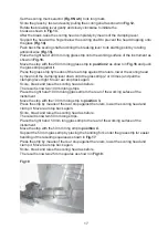
Страница 17: ...own onto the glass strip 2 or 3 times and pull the clamping lever tight Move rear stop back again Score break and raise the scoring head as before The result is now two 100 mm long strips Place the right hand 100 mm long glass strip to the rear of the working suface of the instrument Move the stop with the 100 mm long strip to position 3 Press the strip by means of the rear stop against the rulers...

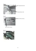
Страница 18: ...18 Freshly broken side Freshly broken side Fig 21 Fig 22 Notch of the front stop Notch of the rear stop Fig 23 ...

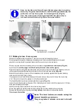
Страница 19: ...w held firmly between the two stops Open and close the rear stop 2 or 3 times to ensure the glass is correctly positioned The handling fork lies loose underneath the square Fig 23 Lower the scoring head by means of the clamping lever down onto the square 2 or 3 times then pull clamping lever tight Set the scoring mark selector to its short or long mark Score the glass by quickly and evenly pulling...

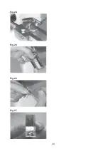
Страница 20: ...20 Fig 24 Fig 25 Fig 26 Fig 27 ...

Страница 21: ...ft and one to the right Each of the knives have a knife edge and a knife shoulder Fig 24a Keep the knives together as a pair Take them from the handling fork as shown in Fig 25 Do not allow the knives to touch Turn the right hand knife Fig 26 to bring the knife edge side by side with the knife edge of the left hand knife Both knives are know placed together as a pair and visual evaluation can be c...

Страница 22: ...22 Fig 28 Fig 29 Fig 30 Fig 31 Right hand knife Left hand knife Fig 32 ...

Страница 23: ...t be used is shown in Fig 30 This has been picked up incorrectly leaving a finger print over the knife edge In Fig 31 a pair of knives is shown broken and placed side by side according to chapter 5 3 The detail Fig 32 shows the knife shoulder of both knives The right hand knife edge was opposite the left hand knife shoulder during breaking and the left hand knife edge was opposite the right hand k...

Страница 24: ... influences both knife shoulders contrary Turn it to the left left knife shoulder becomes bigger right knife shoulder becomes smaller Turn it to the right right knife shoulder becomes bigger left knife shoulder becomes smaller Fine adjustment B rotatable a half turn to the right and a half turn to the left This movement influences both knife shoulders simultaneously Turn it to the left both knife ...

Страница 25: ...art with follow the scoring and breaking procedure as described in chapter 5 2 and 5 3 Having a closer look at the knife shoulders as described in chapter 5 4 then proceed turning fine adjustment A or B Note Fine adjustments A and B are very sensitive only a small turn within the scale is necessary Note Always begin with fine adjustment B to set both knife shoulders as small as possible Then use a...

Страница 26: ...26 Fig 34 Fig 35 Fig 36 Sliding surfaces ...

Страница 27: ...e the scoring head 7 1 Replacement of the scoring wheel cartridge With frequent use the scoring wheel cartridge should be replaced around once a year To replace raise the scoring head as shown in Fig 36 and place it on the table upside down Using the 2 mm Allen Key provided to open the clamping screw for the scoring wheel cartridge as shown in Fig 37 and pull out complete cartridge as shown in Fig...

Страница 28: ...28 Fig 39 Fig 40 Fig 41 ...

Страница 29: ...lockwise the pressure can be decreased After turning the screw in the required direction a quater to a half turn replace the scoring head and make a test score on a piece of glass Repeat until the pressure is correct The pressure is correct Fig 40 one faint smooth line without glass splinters The pressure is too strong Fig 41 a groove and glass splinters can be seen The pressure is not enough when...

Страница 30: ...30 Fig 42 Fig 43 Fig 44 Fig 45 Hotplate Wax bath ...

Страница 31: ...te with the knife edge overhanging the edge of the hotplate as shown in Fig 43 The attachment surfaces of the Truf are coated with molten wax by putting it onto the wax bath as shown in Fig 43 The Truf is then brought into contact with the pre warmed knife and slid up until it is levelled with the knife edge as shown in Fig 44 The Truf is held in this position for a second or two until the wax has...

Страница 32: ...52 25 Knife boxes 3 pcs 70 52 27 Scoring wheels for Knifemaker1 3 pcs 70 66 99 Scoring wheel cartridge for Leica EM KMR2 KMR and Knifemaker II Recommended accessories 70 54 01 LEICA EM MP 115 230VAC complete with metal spatula and 500g dental wax Hotplate with 3 different temperatures for mounting TRUFS on glass knives and for staining and drying of semithin sections on glass slides Leica best sol...

Страница 33: ...o pre set Scoring Angle 45 Glass Strips Special glass for Ultramicrotomy Cryo ultramicrotomy and Histology Length 400 mm Width 25 mm Thickness 6 4 8 10 mm Scoring Wheel Tungsten carbide in cartridge Leica EM KMR 2 Dimensions and Weight Length 400 mm Depth 280 mm Height 280 mm Weight 11kg ...

Страница 34: ...34 Leica Mikrosysteme GmbH Tel 43 1 48899 Hernalser Hauptstrasse 219 Fax 43 1 48899 350 A 1170 Wien Austria www em preparation com ...

Отзывы: