


2
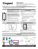
PLUG N’ GO OPERATION (PNG)
All loads are automatically bound to the
LMDM-101.
The rocker paddle on the LMDM-101
controls all loads on the DLM Local
Network. Tap the top of the rocker to
turn ON all loads to the last light level.
Tap the bottom to turn OFF all loads.
Dimmable loads dim (ramp down or up)
in response to a press and hold of the
appropriate portion of the rocker paddle.
Switched loads turn OFF when ramped
down below 50% and turn ON when
ramped up above 50%.
To change the loads controlled by the
LMDM-101 see UNIT ADJUSTMENT.
UNIT ADJUSTMENT - PUSH N’ LEARN (PNL)
Load Binding Procedure
A configuration button allows access to our patented Push n’ Learn™ technology to change the binding relationship between switch
buttons and loads.
Step 1 Enter Push n’ Learn
1. Using a pointed tool, press and hold the configuration button for 3 seconds, until the Red LED on the switch
begins to blink.
2. When you release the switch’s configuration button, the red LED on other communicating DLM Local
Network devices begins to blink.
3. The DLM Local Network is now in PnL mode. The Red LEDs continue to blink until you exit PnL mode.
4. All loads in the room turn OFF after entering PnL. After one second, one load turns ON. This is Load #1,
which is bound to switch button #1 as part of the Plug n’ Go factory default setting. The Blue LED will be ON
for all devices that are bound to this load.
Step 2 Load selection
1. To step through the loads connected to the DLM Local Network, press and quickly release the configuration
button. The first press turns OFF load 1 and turns ON load 2. The next press turns OFF load 2 and turns
ON load 3, and so forth. As each load turns ON note which devices (switch buttons, sensors, etc.) are
showing the blue LED. These devices are currently bound to the load that is ON.
2. To unbind a switch button or rocker paddle from a load, press the switch button or tap the rocker paddle
while its blue LED is ON. The blue LED turns OFF to indicate the device no longer controls the load that is
currently ON.
3. Pressing the switch button or rocker paddle again while the load is ON rebinds the load to the device and
the blue LED illuminates.
Step 3 Exit Push n’ Learn
1. Press and hold the configuration button until the red LED turns off, approximately 3 seconds.
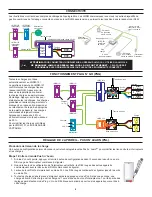
Loads
Loads
4
5
Line Voltage
LMRC-213
LMRC-102
J-Box
Switch
Line
Voltage
Line Voltage
LMDM-101
LMDM-101
LMDM-101
0-10 Volt
Ballast
0-10 Volt
Ballast
0-10 Volt
Ballast
A
C
B
A
B
1
2
3
Loads:
1,2,3,4,5
Loads:
1
2,3,4,5
This device complies with part 15 of the FCC Rules. Operation is subject to the following two conditions: (1)This device may not cause
harmful interference, and (2) this device must accept any interference received, including interference that may cause undesired operation.
NOTE:
This equipment has been tested and found to comply with the limits for a Class A digital device, pursuant to part 15 of the FCC Rules.
These limits are designed to provide reasonable protection against harmful interference when the equipment is operated in a commercial
environment. This equipment generates, uses, and can radiate radio frequency energy and, if not installed and used in accordance with the
instruction manual, may cause harmful interference to radio communications. Operation of this equipment in a residential area is likely to
cause harmful interference in which case the user will be required to correct the interference at his own expense.


