


KEOR T EVO
Installa
tion & Oper
ation M
anual
Description of the Symbols Used in the Manual
This symbol points out the instructions which are especially important.
This symbol points out the risk of electric shock if the following instruction is
not followed.
This symbol points out the instructions, which may result with injury of the
operator or damage of the equipment if not followed.
All packing material must be recycled in compliance with the laws in force in the
country where the system is installed.
Description of the Symbols Used in the Manual
UPS: Uninterruptible Power Supply
ESD: Emergency Switching Device
RS232: Serial Communication Protocol
RS485: Serial Communication Protocol
MODBUS: Modicon Communication Protocol
SNMP: Simple Network Management Protocol
V: Volt
A: Ampere
P: Power
For Mains Supply, Auxiliary Mains Supply, Output, Battery Circuit Breaker and Maintenance Bypass Circuit
Breaker;
“ON”: Closing the Circuit
“OFF”: Opening the Circuit
15
15
KEOR T EVO
Installa
tion & Oper
ation M
anual
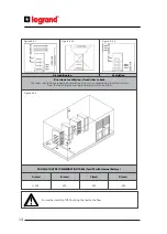
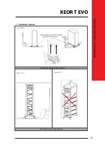
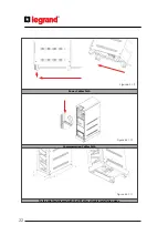
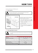
The UPS should be mounted on a concrete surface and non-combustible surface.
In order to pr
ofit
from optimal ventilation, the side panels must remain in place for UPS
with internal battery.
Optimal battery life time is reached when battery ambient temperature is kept between
15°C and 25°C. Operating battery at 30°C ambient temperature compared to 20°C will
divide by factor 2 battery life time. Room thermal management as
specified
above is
then necessary to avoid battery life time reduction. The Battery warranty does not apply
if the temperature in the room exceeds 25°C.
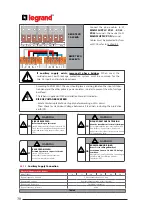
When dual inputs is used:
• Separate Neutral conductor is necessary to be supplied for each input: Common
Mains Input and Auxiliary Mains Input
• The two inputs should be supplied by the same MV/LV transformer source. If this is
not the case, an insulation transformer should be added in the auxiliary mains line
upstream the UPS.
• Separate protection is necessary for each input line.
5.3.
Storage
Please store the UPS in an environment where the temperature is between -25°C +55°C, no receipt of
direct sunlight, far from the heating, in a dry place.
Environmental humidity must be between 20-95% (non-condensing).
Recommended storage temperature, humidity and altitude values are listed on the Appendix-1 Technical
Specifica
tions section.
If the batteries will be stored for longer than 6 months, they shall be charged periodically. Charge period
depends on the storage temperature, as shown below:
• Every 9 months if the temperature is below 20°C,
• Every 6 months if the temperature is between 20°C and 30°C,
• Every 3 months if the temperature is between 30°C and 40°C,
• Every 2 months if the temperature is over 40°C
For long storage duration; please follow up the instructions of installation described in Section 6, start-up
UPS described in Section 8 and charge the batteries at least 10 hours.
5.4.
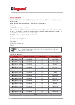
Electrical Requisites
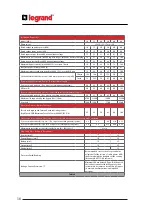
The installation must comply with national installation regulations.
The electrical distribution panels for common mains supply voltage and auxiliary mains supply voltage
inputs must have a protection and disconnection system. Disconnection devices used in these panels
shall disconnect all line conductors simultaneously. The following table shows the recommended size
of common mains supply voltage and auxiliary mains supply voltage input protection devices (thermal,
mag
netic and diff
erential) and the cable cross-sections for the linear loads. The energy quality of the
electrical network should comply with the individual voltage harmonics compatibility lev
els defined b
y
IEC 61000-2-2. For more severe conditions, a power quality audit is required to check compatibility during
UPS commissioning by authorized LEGRAND UPS Technical Service Personnel.
of common mains supply voltage and auxiliary mains supply voltage input protection devices (thermal,
mag
netic and diff
erential) and the cable cross-sections for the loads.
Содержание KEOR T EVO 10-60 KVA
Страница 1: ...KEOR T EVO 10 60 KVA Installation Operation Manual LE11585AC ...
Страница 93: ......