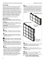
Installation Instructions
TILD1X05US / TILD1X1US / TILD1X2US / TILVAB2
9
8.
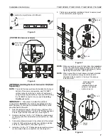
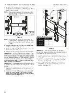
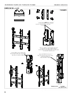
Slide the left (A-Left) and right (A-Right) adjustment washers
into place behind the partially installed lag screws. (See
Figure 12)
Figure 12
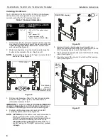
9.
Check the level of the mount at the bottom of the teardrop
slots. (See Figure 13)
10. If the mount is not level, slide or use a dead blow hammer
to lightly tap the spacer into place. This will lift the mount up
as the lag screw rides in the washer’s angled slot. (See
Figure 13)
11. When the mount is leveled, tighten the lag screws (C). (See
Figure 13)
Figure 13
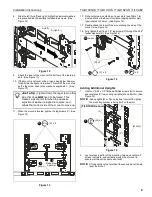
12. Drill pilot holes in centerline of lower slots (see Table 1 for
size) and follow fastener information (appropriate for wall
type) located in Table 1. (See Figure 14)
13. Double check the level of the mount along the side of the
mount. (See Figure 14)
14. Fully tighten the 5/16 x 2-1/2" lag screws (C) through the 5/16"
fender washers (D). (See Figure 14)
Figure 14
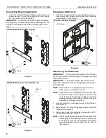
Adding Additional Uprights
1.
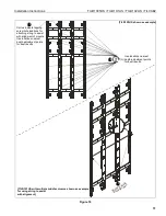
Use four 10-24 x 1/2" flathead Phillips screws (Q) to secure
spacer plates (P) to mounting uprights (M and M or N). (See
Figure 15)
NOTE:
Add uprights (M or N) one by one from left to right as
the mounting system is being built on the wall.
Figure 15
2.
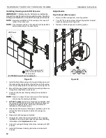
Lay levels across flat of the mounting holes and center-of-
screen indicators, and vertically along side of mount to
ensure wall mount is square and level.
NOTE:
Lift up slightly on the far side of the second mount to help
level the mount.
8
A (right)
A (left)
Just a tip -
Tighten down the lag screw on the
side that does
NOT
need to be raised. This
creates a pivot point for when the opposite
adjustment washer is tapped into place, and
allows that correct side of the mount to move up.
Level
Dead blow
hammer
11
(C) x 2
9
10
14
(C) x 2
12
x 2
13
Level
(D) x 2
1
(Q) x 4
(P)
(L)
(M)
(M or N)
(TILD1X2US shown)


