


TILD1X05US / TILD1X1US / TILD1X2US / TILVAB2
Installation Instructions
10
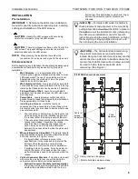
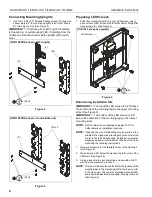
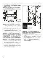
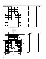
3.
Mark mounting hole in top mounting slot along the
horizontal line marked in Step 3 of
Installing First Mount
Section. (See Figure 16)
NOTE:
The mounting holes are 18.06" apart on-center for
center (M) and center (M) or center (M) and right (N)
uprights. (See Figure 16)
Figure 16
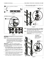
NOTE:
Drill two pilot holes (see Table 1 for size) at each
location marked in Step 3 (See Figure 16) and follow
fastener information (appropriate for wall type) located
in Table 1.
4.
Hold the adjustment washers in place by hand and tighten
the fasteners at the top of the mount.
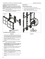
5.
Drill lower pilot holes at attachment locations and use same
fasteners used at top of mount.
6.
Install two fasteners through lower part of mount and tighten.
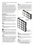
IMPORTANT ! :
For larger LED walls it is helpful to check
placement and alignment of the mounts by putting a few
LED housings in place in the bottom row of the installed
mounts (referencing the LED screen installation manual
for specific instructions) during the mount installation,
checking alignment before removing the housings, and
then continuing the installation.
IMPORTANT ! :
Continually recheck the alignment and
overall flatness of the wall mounts during the installation
process.
7.
Continue the installation process until all wall mounts are
attached.
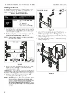
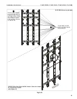
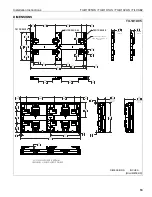
8.
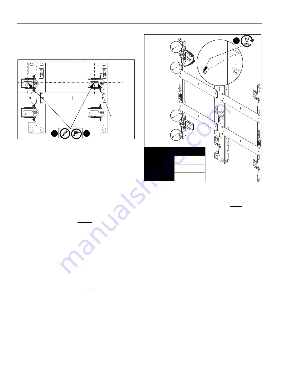
Install one #10 x 1/2" Phillips tapping screw (G) into left
upper LED mounting button hole for each LED screen
space. Install the tapping screws ONLY
on the furthest left
column of mounts
. (See Figure 17)
Figure 17
IMPORTANT ! :
The tapping screws keep the LED
screens from moving side to side, and are ONLY installed
on the furthest left column of mounts.
9.
Using a drill driver makes installation of the tapping screws
(C) easier.
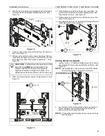
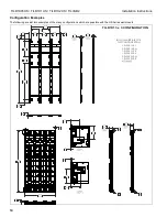
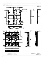
10. Install the remaining #10 x 1/2" self-tapping screws (G) on
the mount, as necessary, to assist in centering the LED
housings. (See Figure 18)
11. Run a string between the self-tapping screws installed in
Step 7
to assist with alignment across long sections of
mounts. (See Figure 18)
2
3
Line showing
mounting slots
for mounts in LED
center of
18.06 inches
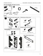
Model
Fastener
TILD1X2US
8
TILD1X1US
4
TILD1X05US
2
[TILD1X1US shown as example]
8
(G)