background image

8/16 


ELIOT Kit STOP&GO Connected 


Cat. N°: 4

 149 54


4. PREPARATION - CONNECTION

 (continued)


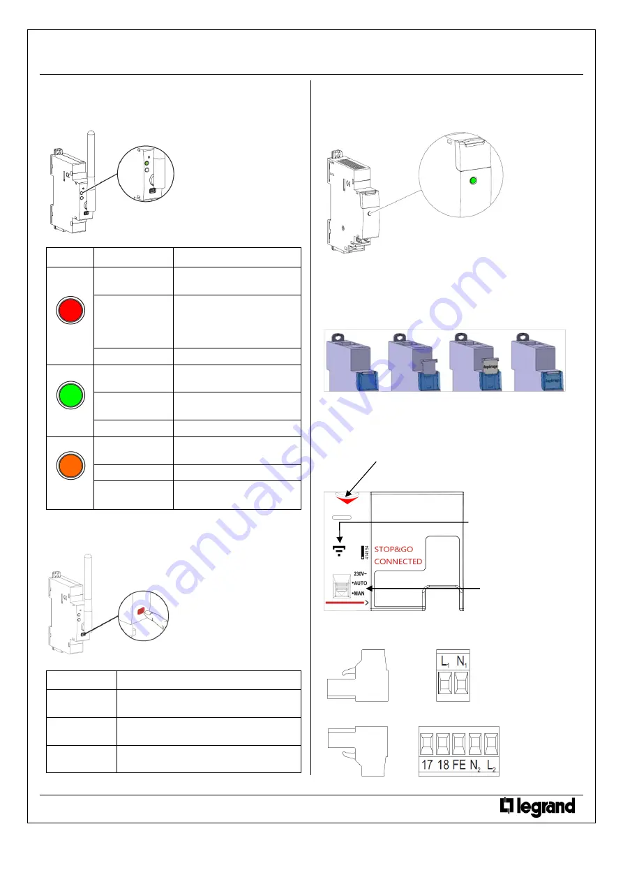
Wi-Fi module signalling led 

(continued): 

. Wi-Fi led: indicates the status of the Wi-Fi Network: 


  Possible states: 

Led colour 

State 

Meaning 

red 

Slow blinking 

No Wi-Fi- network detected or 
connection problems 

Fast blinking 

(pressing the 
multifunction button 
longer than 30 sec.)


Total reset 

[any firmware updates are 
preserved]


Steady 

Wi-

Fi signal ≤ 25%


green 

Slow blinking 

Scanning for Wi-Fi network 

(during association procedure)


Fast blinking 

Programming via WPS button 
of the Wi-Fi router 

Steady 

Wi-Fi signal 

≥ 50%


orange 

Slow blinking 

Interface not associated to any 
network 

(Factory configuration)


Fast blinking 

Manual Programming mode 

Steady 

Wi-Fi signal between 25% and 
50%  

Wi-Fi module front face button: 

. It is used to put the Wi-Fi interface in programming mode or to 
restore factory settings: 


  Possible states: 

Pressing time 

Action 

t ≈ 3 sec.


Wi-Fi interface put in configuration mode via 
WPS button 

t ≈ 7 sec.


Wi-Fi interface put in configuration mode via 

“Manual procedure”


t > 30 sec. 

Wi-Fi interface total reset 

[any firmware updates are preserved]


4. PREPARATION - CONNECTION

 (continued):


Power supply module signalling led: 

. Indicates the status of operation of the supplier: 


-


Steady green 

 system OK 

-


Steady off 

 supplier malfunctioning  

Labelling: 

. Circuit identification by way of a label inserted in the label holder 
situated on the front of the Stop&Go and of the Power supplier. 


5. GENERAL CHARACTERISTICS 

Stop&Go marking: 

. Front side marking: by permanent pad printing 


Terminals marking: 

. Upstream terminal-block: by permanent ink pad printing. 


. Downstream terminal-block: by permanent ink pad printing. 


Technical data sheet: F02465EN/01 

Updated: 28/03/2019 

Created: 06/10/2016 


Red arrow to indicate that the front face of 
the device can be put down


“ELIOT product” symbol


AUTO/MAN Selector


Содержание 4 149 54

Страница 1: ...non permanent fault It reports the information through the Smartphone app Allows the user to remotely switch it ON In case of recurrent non permanent faults the Stop Go will not allow some remote comm...

Страница 2: ...e kit to connect at the downstream of the supplier indifferently in one of the two dedicated ports Supply of the Wi Fi Interface Mandatory in 12 VDC via the specific Power supply module and specific s...

Страница 3: ...install a specific protection upstream of the Stop Go because it is self protected 4 PREPARATION CONNECTION continued Wiring diagrams continued Power supply module protected by an MCB protected by a...

Страница 4: ...lip the Wi Fi module and the power supply on a different DIN row than the Stop Go module 4 PREPARATION CONNECTION continued Diagnostic procedure Once the kit assembly and the electrical connections ha...

Страница 5: ...the Stop Go the Stop Go power handle is down and the isolating handle is up and the Stop Go led flashes quickly in red 7 2 An alert message is displayed 7 3 Press on TURN ON 4 PREPARATION CONNECTION...

Страница 6: ...site information displayed by the Stop Go continued Device handle status continued Operation sequences continued In case of an Unwanted tripping of the associated device and during the verification o...

Страница 7: ...ows to remotely control the Stop Go via the Smartphone app reclosing of the associated device following a fault MAN on site manual control only by the handle of the Stop Go isolating and power handles...

Страница 8: ...rogramming mode or to restore factory settings Possible states Pressing time Action t 3 sec Wi Fi interface put in configuration mode via WPS button t 7 sec Wi Fi interface put in configuration mode v...

Страница 9: ...ne and laser marking Lateral side marking by laser left side Standard and programming information right side cabling and traceability information Technical data sheet F02465EN 01 Updated 28 03 2019 Cr...

Страница 10: ...ype Measurement type Value dBm 802 11b 1Mbps RMS 18 2 802 11g 54Mbps RMS 16 2 802 11n 72 2Mbps RMS 16 2 Characteristics of the fault detection Rd0 non operating rated resistance between the live parts...

Страница 11: ...ce against solid and liquid bodies IP 40 IEC EN 60529 Class II front panel with faceplate Resistance to sinusoidal vibrations According to IEC 60068 2 6 Axis x y z Frequency range 5 100 Hz duration 90...

Страница 12: ...ream of the associated device to the Stop Go and to protect the power supply module with a fuse holder or an MCB see Wiring diagrams Supply of the ADSL Wi Fi Box The Wi Fi module communicates with an...

Страница 13: ...1 2003 corr Feb 2004 A1 2004 A11 2005 A12 2008 Electrical accessories Circuit breakers for overcurrent protection for household and similar installations Part 1 Circuit breakers for a c operation IEC...

Страница 14: ...ing switch can be modified to 2 auxiliary contacts 1 module cat n 4 062 66 Electronic EMS CX3 Auxiliary contact Fault signalling module cat n 4 149 29 Control auxiliaries It is forbidden to associate...

Страница 15: ...ing command closing of the circuit not allowed Close manually the Stop Go 4 A too recurrent non permanent fault has been detected Remote reclosing command closing of the circuit not allowed Contact yo...

Страница 16: ...n MAN mode Remote reclosing command closing of the circuit not allowed Put selector in AUTO position 8 Stop Go in locked position Remote reclosing command closing of the circuit not allowed If it is p...

Отзывы: