background image

13

WORKSHOP SPECIFICATIONS

XL³ 160

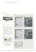
The upper and lower side panels of the 

cabinet can be cut in order to insert 

cables. Two guidelines are marked 

to give the cutting heights for 50 and 

65 mm ducting.

The side panels are easy to cut using a jigsaw

Plate Cat. No. 0 200 71 with knockout cable 

entries can be installed instead of an upper or 

lower side panel.

The DLP/cabinet joining strip 

Cat. No. 0 201 60 improves the 

finish and increases the cable 

spreading volume.

The cables can be anchored at the back of the cabinets using Colson™ cable ties.

Knocking out the feedthroughs

Anchoring the cables

5

 INSERTING AND FIXING CABLES

WWW.LEGRAND.COM

Содержание 0 200 02

Страница 1: ...WORKSHOP SPECIFICATIONS XL 160 DISTRIBUTION CABINETS THE GLOBAL SPECIALIST IN ELECTRICAL AND DIGITAL BUILDING INFRASTRUCTURES ...

Страница 2: ...t other things a large amount of space for wiring wide connection areas 200 mm top and bottom faceplates a removable chassis clever solutions for cable feedthrough and fixing fasteners that are common to the whole range all with a modern design and finish LEGAL INFORMATION Presentation pictures do not always include Personal Protective Equipment PPE but this is a legal and regula tory obligation t...

Страница 3: ...inets 20 Preparing the cabinets 22 Mounting devices 23 Wiring and connection 24 Installation and finishes 27 Flush mounting cabinets 30 Preparing the cabinets 32 Flush mounting 33 Mounting devices 34 Wiring and connection 35 Finishes 37 Distribution 38 Supply busbars terminal blocks distribution terminals and modular distribution blocks 38 Appendices 41 Fitting key barrels 41 Dimensions 42 Accesso...

Страница 4: ...ance operations and to refer to the Documentation If you have any questions or require clarification please contact Legrand Group The installation use and maintenance of the enclosures and their components must be carried out by qualified trained and authorized personnel in accordance with the regulations in force in each country RISK OF ELECTRIC SHOCK BURNS AND EXPLOSION People working on the ins...

Страница 5: ...ly encountered However it is always the customer s responsibility to verify and validate that Legrand products are suitable for its installation and use The customer must ensure proper installation maintenance and operation of the equipment to avoid any risk of injury to person nel or damage to property in the event of product failure especially for applications that require a very high level of s...

Страница 6: ...me can be dismantled XL 160 cabinets also offer original solutions for holding and running the wiring a large working area and a high quality finish CHARACTERISTICS Class II insulated cabinet Short circuit resistance Ipk 20 kA IP 30 without door IP 40 with door and IP 43 with door and seal IK 04 without door IK 07 with door Door opening angle 120 Conforming to standards IEC 61439 2 and IEC 61439 3...

Страница 7: ...mm 450 600 750 900 1050 900 1050 Number of modular rows 2 3 4 5 6 3 4 Number of modules 48 72 96 120 144 72 96 Raised doors Solid 0 202 52 0 202 53 0 202 54 0 202 55 0 202 56 0 202 55 0 202 56 Glass 0 202 62 0 202 63 0 202 64 0 202 65 0 202 66 0 202 65 0 202 66 Flat doors Solid 0 202 72 0 202 73 0 202 74 0 202 75 0 202 76 0 202 75 0 202 76 Glass 0 202 82 0 202 83 0 202 84 0 202 85 0 202 86 0 202 8...

Страница 8: ...for wiring XL3 160 cabinets can be completely dismantled Simply remove the faceplate support frame and all the side panels XL3 160 offers you three possibilities to suit your preferred way of working Removing the side panels individually CLASS II INSULATED CABINETS Removing the chassis Removing the faceplate support frame and side panels PREPARING THE CABINETS XL3 160 TERMINAL BLOCK TYPE Enclosure...

Страница 9: ...e is full access to the wiring With the faceplates removed the chassis can be removed from the cabinet after unscrewing the 4 retaining screws Each side panel is held in place by 2 screws It is very easy to work on the chassis once it has been removed from the cabinet WWW LEGRAND COM It is also possible to remove the side panels independently In this case it is not necessary to remove the faceplat...

Страница 10: ... row see page 34 Vistops with side front handle are supplied with the accessories needed to locate the handle on the outside of the enclosure Example of mounting a Vistop with side handle Mounting the DPX on the adaptor Mounting the assembly on the chassis by removing the plastic rail support A template is provided with the side front handle for drilling the side panel 1 MOUNTING THE DPX 2 MOUNTIN...

Страница 11: ... three phase 60 A with plates Cat Nos 4 011 82 91 or subscriber circuit breaker Linky compatible single phase meter Cat No 4 011 81 Kit Cat No 0 202 31 supplied with connection plate for subscriber circuit breaker Linky three phase electronic meter The plates are fixed on the chassis uprights using the screws provided M6x10 mm 4th and 14th holes for kit Cat No 0 202 30 1st and 13th holes for kit C...

Страница 12: ...ical ducting 40x60 Thesupportscliponinthesame way as the vertical wiring guide rings The ducting is fixed using the insulating rivets provided The cabinet chassis can be connected to earth using the threaded holes XL3 160 cabinets are supplied with a brass terminal block for protective conductors with 2 x 35 mm2 holes and 36 x 10 mm2 holes As the cabinet is reversible the terminal block can be pla...

Страница 13: ...X terminal blocks for protective conductors see below Legrand IP 2X terminal blocks are installed on 12 x 2 flat bars Cat No 0 048 19 fixed either on the built in insulating supports or on supports Cat No 0 200 50 The slots provided at the back of the cabinet allow these bars to be installed horizontally or vertically on the right or the left Screw the supports Cat No 0 200 50 to the back of the c...

Страница 14: ...3 supply busbar for cabinets with 2 3 and 4 rows Cat Nos 4 050 03 04 05 Three phase vertical distribution using auto VX3 supply busbar available in 63 A 3 4 5 and 6 rows or 125 A 4 5 and 6 rows These models are equipped with automatic output terminals XL3 160 cabinets can take various horizontal and vertical distribution systems 4 052 24 4 052 40 Three phase horizontal distribution using 125 A plu...

Страница 15: ... easy to cut using a jigsaw Plate Cat No 0 200 71 with knockout cable entries can be installed instead of an upper or lower side panel The DLP cabinet joining strip Cat No 0 201 60 improves the finish and increases the cable spreading volume The cables can be anchored at the back of the cabinets using Colson cable ties Knocking out the feedthroughs Anchoring the cables 5 INSERTING AND FIXING CABLE...

Страница 16: ...s are used to attach and detach the cabinets Knock out the holes corresponding to the position of the lugs Place the special nut and the plastic cover in position then screw in the lug from the back of the cabinet INTERNAL AND EXTERNAL FIXING CENTRES CABINET COMBINATION Cabinets A mm B mm C mm Vertical Fixing centre mm Horizontal Fixing centre mm 4 018 02 500 305 343 107 325 4 018 03 650 455 493 1...

Страница 17: ...evices a plastic marking strips Cat No 3 397 55 24 modules or Cat No 3 397 56 36 modules are available as accessories supplied with the sets of labels Sealing the faceplate in locked position Remove the blanking plates then fit the hinges on the frame The door release is fitted on the opposite side to the hinges using the 2 screws provided When fitting the handle it is essential to fit the metal b...

Страница 18: ...ial link conductor and the circuits supplying the control and signalling units must be protected with devices providing protection against indirect contact The seal must join up at the bottom of the door A wide range of finishes and accessories For more information consult workshop specifications EN 61439 1 2 available from www legrand com ecatalogue 4 ACHIEVING IP 43 5 AUXILIARIES ON DOOR All met...

Страница 19: ...e cutting limits on the side panels of the cabinets to be joined together and mark where the 4 holes are to be drilled Use the terminal block supports as marking guides Drill both sides at the same time Ø 6 5 mm Cut the side panels to make the opening for inserting the wiring After refit the drilled and cut side panels place the 4 screws and 4 M6 nuts in position but do not tighten them fully VERT...

Страница 20: ...cabinets Position the cabinets on their sides to align them perfectly then carry out the final tightening The joined unit can be reinforced using using kit Cat No 0 200 22 Kit Cat No 0 200 22 The kit strengthens joining by bolting the 2 chassis together 2 COMPLYING WITH CLASS II 3 STRENGTHENING JOINING Space to be insulated with a seal on the back of the cabinets 25 mm 25 mm 100 mm ...

Страница 21: ...19 WORKSHOP SPECIFICATIONS XL 160 WWW LEGRAND COM Notes ...

Страница 22: ...king area and a high quality finish CHARACTERISTICS Class I metal cabinet Short circuit resistance Ipk 35 kA IP 30 without door IP 40 with door and IP 43 with door and seal IK 07 without door to IK 08 with door Door opening angle 120 Conform to standards IEC 61439 2 and 61439 3 Fireproof according to IEC 60695 2 11 750 C 5 s Suitable for installations in public buildings Can take devices up to 160...

Страница 23: ...mm 450 600 750 900 1050 Number of modular rows 2 3 4 5 6 Number of modules 48 72 96 120 144 Raised doors Solid 0 202 52 0 202 53 0 202 54 0 202 55 0 202 56 Glass 0 202 62 0 202 63 0 202 64 0 202 65 0 202 66 Flat doors Solid 0 202 72 0 202 73 0 202 74 0 202 75 0 202 76 Glass 0 202 82 0 202 83 0 202 84 0 202 85 0 202 86 WWW LEGRAND COM ...

Страница 24: ...es a cable entry plate and a brass terminal block for connecting protective conductors The cardboard packaging can be re used for delivery to the site For ease of wiring it is possible to remove all the side panels XL3 160 offers you two possibilities to suit your preferred way of working Removing the side panels individually Removing the chassis PREPARING THE CABINETS 1 WIRING AT THE BACK OF THE ...

Страница 25: ... cabinet A template is provided with the side handle for drilling the side panel With the faceplates removed the chassis can be removed from the cabinet after unscrewing the 4 retaining screws one at each end of the chassis It is very easy to work on the chassis once it has been removed from the cabinet The DPX 160 is mounted in a low position on a rail remove the insulating supports and refit the...

Страница 26: ...at No 0 367 74 to fix the ducting directly on the uprights Insert the ring on the side of the support then push it towards the back Holding vertical wiring in place XL3 160 cabinets take guide rings Cat No 0 200 94 for horizontal wiring These rings are fixed directly below the rails Lina 25 ducting Supports Cat No 0 200 70 are used for installing Lina 25 vertical ducting 40 x 60 The supports clip ...

Страница 27: ...r on the integrated supports or on the guide rings Cat No 0 200 94 Bar for protective conductors pre installed in XL3 160 cabinets Guide rings Cat No 0 200 94 enable an additional brass bar Cat No 0 373 00 to be installed between the rows Metal XL3 160 cabinets can take one or two 12 x 2 flat bars Cat No 0 048 19 for IP 2X terminal blocks Cut and drill bar Cat No 0 048 19 Fix the bar on the plasti...

Страница 28: ...ine Plate Cat No 0 200 21 with knockout cable entries 22 x Ø 20 mm entries and 2 x Ø 32 mm entries is fitted in the same way Metal cabinets can take at the top and the bottom the special cable fixing support Cat No 0 200 35 Cables anchored on support Cat No 0 200 35 using Colson cable ties all Colsonand Colring cable ties can be used 4 INSERTING AND FIXING CABLES The DLP cabinet or housing service...

Страница 29: ...ND FINISHES Fit the clip nut Screw on the lug in the required position The cabinets can be joined vertically or horizontally INTERNAL AND EXTERNAL FIXING CENTRES CABINET COMBINATION Cabinets A mm B mm C mm Vertical Fixing centre mm Horizontal Fixing centre mm 0 200 02 500 305 343 107 325 0 200 03 650 455 493 107 325 0 200 04 800 605 643 107 325 0 200 05 950 755 763 137 325 0 200 06 1100 905 943 10...

Страница 30: ...provided on both sides of the cabinet Rotary slider As well as the label holders on all modular devices a plastic marking strips Cat No 3 397 55 24 modules or Cat No 3 397 56 36 modules are available as accessories supplied with the sets of labels Sealing the faceplate in locked position Insert and fix the hinges in the slots on the side panels The door release is fitted on the opposite side to th...

Страница 31: ...directly onto the faceplate support inside the enclosure When the plastic cover is removed up to 4 conductors can be inserted in the enclosure For class II installations the cables supplying the control and signalling units must be treated as class II and attached and protected using a continuous insulated sheath to prevent them being pulled out and becoming accidentally detached If the control vo...

Страница 32: ...oved individually removable chassis frame can be dismantled XL 160 cabinets also offer original solutions for holding and running the wiring a large working area and a high quality finish CHARACTERISTICS Class II insulated cabinet Short circuit resistance Ipk 20 kA IP 30 without door IP 40 with door IK 04 without door IK 08 with door Door opening angle 120 Conforming to standards IEC 61439 2 and I...

Страница 33: ... the finishing frame mm 695 845 995 1145 995 1145 External width with the finishing frame mm 670 670 670 670 670 670 Box height mm 640 790 940 1090 940 1090 Box width mm 617 617 617 617 617 617 Number of modular rows 3 4 5 6 3 4 Number of modules 72 96 120 144 72 96 Flat doors Solid 0 202 73 0 202 74 0 202 75 0 202 76 0 202 75 0 202 76 Glass 0 202 83 0 202 84 0 202 85 0 202 86 0 202 85 0 202 86 WW...

Страница 34: ...emoving the finishing frame provides a wide access area for wiring at the back of the box XL3 160 offers you two possibilities to suit your preferred way of working Removing the faceplate support finishing frame Removing the chassis PREPARING THE CABINETS The 4 chassis retaining screws can be accessed when the finishing frame has been removed The chassis can be removed from the cabinet so that the...

Страница 35: ... out the holes for the mounting lugs according to the thickness of the wall After cutting out the cable feedthroughs and positioning the enclosure insert the mounting lugs and tighten them Pull up the masonry anchors Open up the cable feedthroughs wide pre cut sections make this task easier 1 FIXING IN A MASONRY WALL 2 MOUNTING IN A HOLLOW PARTITION WWW LEGRAND COM ép 30 à 72 mm ép 10 à 30 mm MINI...

Страница 36: ... rails to optimise the space when installing modular devices next to the incoming circuit breaker Mounting with a plate Mounting with a plate and the rail height spacer next to it Installation of a modular product at the same level as the DPX 160 Kit Cat No 0 202 30 for subscriber circuit breaker only single phase 90 A or three phase 60 A with plates Cat Nos 4 011 82 91 or subscriber circuit break...

Страница 37: ...a special support at the top and bottom for fixing cables Fitting a guide ring for horizontal wiring Cables anchored using cable ties all Colson and Colring cable ties are compatible Holding vertical wiring in place Lina 25 ducting Supports Cat No 0 200 70 are used for installing Lina 25 vertical ducting 40 x 60 The supports for Lina 25 ducting clip on in the same way as the vertical wiring guide ...

Страница 38: ...lat bars Cat No 0 048 19 for IP 2X terminal blocks Bar for protective conductors pre installed in XL3 160 Horizontal wiring guide rings Cat No 0 200 94 enable an additional brass bar Cat No 0 373 00 to be installed between the rows Cutting out and drilling bars Cat No 0 048 19 to create a horizontal terminal block The support integrated at the back of the cabinet is used to fix the bars both horiz...

Страница 39: ...ish The faceplates are locked using a 1 4 turn fastening their shape makes them easy to handle Sealing the faceplate in locked position Remove the blanking plates then fit the hinges on the frame The door release is fitted on the opposite side to the hinges using the 2 screws provided When fitting the handle it is essential to fit the metal bracket so that the door locks correctly 1 FACEPLATES AND...

Страница 40: ...stribution in rows DX3 auto devices are used to connect supply busbars without the need for tools see below DISTRIBUTION Totally universal in their application this type of terminal block can be used to distribute up to 100 A on between 4 and 33 outputs depending on the catalogue number The incoming cross section is between 4 and 25 mm2 and that of the outputs between 4 and 16 mm2 These terminal b...

Страница 41: ...pply busbar for cabinets with 2 3 and 4 rows Cat Nos 4 050 03 04 05 Three phase vertical distribution using auto VX3 supply busbar available in 63 A 3 4 5 and 6 rows or 125 A 4 5 and 6 rows These models are equipped with automatic output terminals XL 160 cabinets can take various horizontal and vertical distribution systems Three phase horizontal distribution using 125 A plug in HX3 supply busbar ...

Страница 42: ...minals on the same row These combine compactness and high connection capacity They clip onto the 3 rails Legrand modular distribution blocks are fully insulated they are used at the supply end of the panel up to 250 A or in subgroups of outputs in panels with a higher power rating Modular single pole distribution blocks total isolation of poles in order to distribute up to 250 A 160 A max in a XL ...

Страница 43: ...oloured adaptor Insert the assembled barrel in the body of the handle Insert the assembled barrel in the body of the handle Large handle enclosures H 1500 mm Small handle enclosures H 1500 mm Once the handle has been dismantled M6 screw the blanking plate is automatically released Combine the adaptor casing and barrel assembly with the black adaptor Insert the pin in the notch towards the front Re...

Страница 44: ...ET DOOR DISTANCE MM METAL GLASS 0 202 52 0 202 62 450 57 53 0 202 53 0 202 63 600 57 53 0 202 54 0 202 64 750 57 53 0 202 55 0 202 65 900 57 53 0 202 56 0 202 66 1050 57 53 METAL GLASS HEIGHT MM CABINET DOOR DISTANCE MM METAL GLASS 0 202 72 0 202 82 450 38 34 0 202 73 0 202 83 600 38 34 0 202 74 0 202 84 750 38 34 0 202 75 0 202 85 900 38 34 0 202 76 0 202 86 1050 38 34 1 INSULATED AND METAL CABIN...

Страница 45: ...43 WORKSHOP SPECIFICATIONS XL 160 WWW LEGRAND COM Notes ...

Страница 46: ...ctors 0 373 00 0 373 00 0 373 00 ACCESSORIES FOR CABLE INSERTION INSULATED METAL FLUSH MOUNTING Cable entry plates can be cut to size 0 200 20 Plate with knockout cable entries 0 200 71 0 200 21 Cable fixing support 0 200 35 WIRING ACCESSORIES INSULATED METAL FLUSH MOUNTING Guide ring for vertical wiring x2 0 200 93 0 200 93 0 200 93 Guide ring for horizontal wiring x1 0 200 94 0 200 94 0 200 94 S...

Страница 47: ...breaker 3 phase meter 0 202 31 Window insulated faceplate for modular devices H 150 mm 0 203 50 Insulated faceplate for DPX3 160 H 300 mm 0 203 60 Solid insulated faceplate H 100 mm 0 203 91 24 module untapped blanking plate can be cut to size 0 200 51 0 200 51 0 200 51 18 module blanking plate can be separated into 1 2 modules 0 016 65 0 016 65 0 016 65 24 module adhesive label holder 3 397 55 3 ...

Страница 48: ...barrels type 455 0 202 92 0 202 92 0 202 92 Key barrels type 1242 E 0 202 93 0 202 93 0 202 93 Key barrels type 2433 A 0 202 94 0 202 94 0 202 94 Seal for IP 43 protection 0 201 30 0 201 30 0 201 30 A4 flexible document holder 0 097 99 0 097 99 0 097 99 Closed rigid document holder 0 365 82 0 365 82 0 365 82 ...

Страница 49: ...IONS XL 160 To know more check export legrand com Alltechnicaldataoftheproductsinsidethisworkshopspecificationsbookareavailable on https www export legrand com en Click on DOCUMENTATION SOFTWARE Documentation WWW LEGRAND COM ...

Страница 50: ...7045 Limoges Cedex France Tel 33 0 5 55 06 87 87 Fax 33 0 5 55 06 74 55 FOLLOW US ALSO ON EXB15003 February 2022 legrand com youtube com user legrand facebook com Legrand twitter com Legrand pinterest com legrandgroup instagram com legrandnews ...

Отзывы: