


14/29
Technical data sheet: S000114123EN-1
Updated:
Created: 18/01/2021
Cat. No(s): 0 026 72/73/74/76/78/79
KNX controller multi-application DIN
7 . COMMUNICATION OBJECTS (continued)
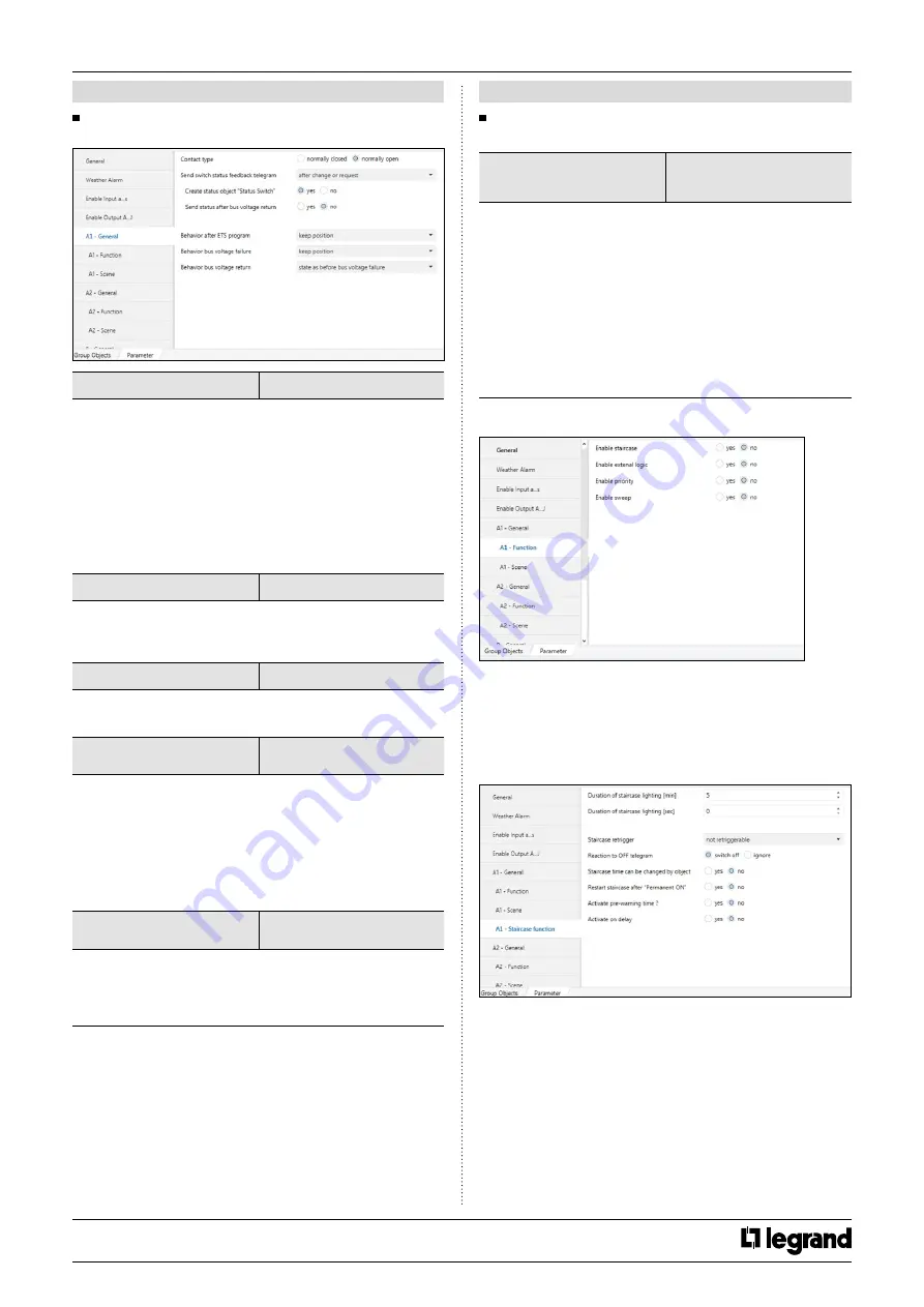
7 .7 "Switch" parameter
7 .7 .1 "A1 - General" parameter
Contact type
*normally open
normally closed
The relays of a switching output can be parameterized as normally
closed or normally open. This feature offers the possibility of inversion
the switching state. Important: This state is only valid for switch
communication object. Other relay function always works normally.
Normally closed contact
Switch state = off (0)
relay contact closed
Switch state = on (1)
relay contact open
Normally open contact
Switch state = off (0)
relay contact open
Switch state = on (1)
relay contact closed
Create status object “Status Switch”
no
*yes
If this parameter select ‘yes’, ETS create another communication object
for use only status switch. The status object can be used to display the
current output switching status on a display.
Send status after bus voltage return
*no
yes
You can use this parameter to send the switching state in the event of
bus voltage recovery.
Behavior after ETS programming or after
ETS reset
*keep position
open contact
close contact
After ETS programming, relay position set the wanted switching
position.
• Set the parameter to “
keep position
”
In this setting, the relay remains in the current state. Any manual
operation occurs in the meantime the switch actuator return its old
position. The device doesn’t know the status of the relay.
• Set the parameter to “
open contact
” or “
close contact
”
The relay contact open or close after bus voltage return.
Behavior bus voltage failure
*keep position
open contact
close contact
When the bus voltage fails, the device set the wanted switching
state of the output. The relay can be open, close or keep position it
occupied prior to the failure. At the same time, the current switching
position of the relay is stored in the devices.
7 . COMMUNICATION OBJECTS (continued)
7 .7 "Switch" parameter (continued)
7 .7 .1 "A1 - General" parameter (continued)
Behavior bus voltage return
keep position
open contact
close contact
*status as before bus voltage failure
When the bus voltage returns, the device set the wanted switching
state of the output.
• Set the parameter to “
keep position
”
In this setting, the relay remains in the current state. Any manual
operation occurs in the meantime the switch actuator return its old
position. The device doesn’t know the status of the relay.
• Set the parameter to “
open contact
” or “
close contact
”
The relay contact open or close after bus voltage return.
• Set the parameter to “
state as before bus voltage failure
”
If the parameter set to “
state as before bus voltage failure
”, then
the relay is set to the value. The value stored at the time of the bus
voltage failure.
7 .7 .2 "A1 - Function" parameter
Above function can be set for each channel. This function;
• Staircase function
• External logic
• Forced position
• Sweep function
Below you can find this functions description.
7 .7 .2 .1 "A1 - Staircase Function" parameter
If you want to use staircase function, you must have been enabled
‘Staircase’ on the function windows. Than required parameters and
communication, objects are visible. The staircase function can be
parameterized for each channel.
Staircase function has a three communication object. These are “
Enable
staircase function
”, “
Staircase lighting duration
” and “
Permanent
ON
”.
CONTENTS


