LAUNCH KWA-300 3D Wheel Aligner Operation Instructions
4-8
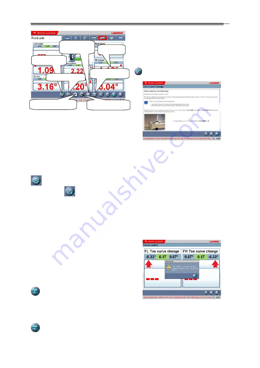
Fig.4.26
[Double click]: Double click (with left key of the mouse)
on the data display forms for camber and toe-in of FL
and FR wheels, the corresponding displayed data will be
enlarged.
[Additional measurement]: This interface provides an
operating platform for special measurement, which can
measure and display left lateral offset, right lateral offset,
axle offset, front setback, rear setback, track width
difference and wheelbase difference, etc.
[Toe-in adjustment for the front wheel steering]: Click
to perform toe-in adjustment for front wheel
steering, and click
to center the steering wheel
(Note: When using two probe rods to perform the
measurement operation, only total toe-in is displayed,
and individual toe-in is not displayed).
[HELP for vehicle adjustment]: Click this button, the
screen will pop up an interface of [HELP for vehicle
adjustment], the different adjusting methods for various
vehicle models have been enumerated in this interface
for vehicle adjustment, the operator can perform the
vehicle adjustment operation according to the operating
methods in the HELP interface.
[Lift up vehicle body]: Sometimes it is required to lift the
vehicle body up in order to be convenient to adjust
front/rear camber and caster. When the vehicle wheels
are lifted up, the inclinometers will move, and the
corresponding measured values will change, too. In this
case, please use Lifting Adjustment function. Click
button, and then lift up the vehicle body according
to the prompts on the screen. The software will
automatically compensate the offset of inclinometer in
order to realize accurate adjustment.
Attention: After adjustment, please remember to click
button, and then put down the vehicle body
according to the prompts on the screen.
[Toe-in curve change] provides the special measurement
methods relative to some vehicle models of
VOLKSWAGE and AUDI, etc. First, the operator must
adjust the toe-in curve changes of these kinds of
vehicles to the standard range, and then Front Axle
Measurement can be performed normally. When [Toe-in
Curve Change] is activated, please click the icon of
, the screen will display the interface as shown in
Fig.4.27.
Fig.4.27
Operating Methods:
1.
Click [Toe-in Curve Change] on the interface of
[Front Axle Measurement] to enter Toe-in Curve
Change interface as shown in Fig.4.25.
2.
According to the prompts on the screen, please
select the appropriate vehicle adjustment tools by
the way of referring to the vehicle adjustment
HELP information for the front toe-in curve change
regulator. Please perform the next operation
procedure after finished.
3.
The vehicle is now in put-down status (position B1).
Adjust the vehicle front toe-in to the allowed scope
according to the standard specifications (see
Fig.4.24). Put up the vehicle with the special tools
equipped according to the prompts on the screen.
Click [NEXT] button, the screen will display the
interface as shown in Fig.4.28.
Fig.4.28
4.
Put up the vehicle (to position B2) according to the
requirements of the manufacturer. The screen
display the interface as shown in Fig.4.29:
Double click
HELP for vehicle
adjustment
Lift up vehicle body
Additional measurement
Toe-in curve change
Compensate
Detailed data
Содержание KWA-300
Страница 1: ......


