9
2.2.2 Recommended Assembly Procedure
1.
Remove the Cable Gland from the insulator and take out the contact.
2.
Slide the Cable Gland onto the cable being terminated.
3.
Carefully strip back the cable insulation by ~33mm taking care not to damage any of the
conductors stranding.
4.
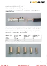
Select the appropriate reduction sleeves (see Table 1 below) and slide on in sequence over
the exposed conductor stranding. All sleeves down to the size recommended for the cable in
use should be used. i.e. for the 50m2 cable, the R120, R95, R70 and R50 sleeves should all
be used. The sleeves fit inside each other to give a gradual reduction in diameter. The flared
end of the sleeves should be against the cable insulation.
Cable Size (mm²)
Reduction Sleeve
Required
Set Screw Torque
Minimum (Nm)
Cable Jacket Strip
Length (mm)
120mm²
120
10.5
33
90 mm²
120 + 95
10.5
33
70mm²
120+95+70
10.5
33
50mm²
120+95+70+50
10.5
33
Table1. Set Screw Assembly Data
Electroustic Ltd www.electroustic.co.uk +44 (0)1908 307200


