7
6.
Following the crimping operation, any contact material deformed between the crimp dies
which prevents the contact assembly from being fitted into the Insulator assembly should be
removed, in line with normal working practices.
7.
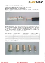
Fit the crimped contact into the insulator and visually align the Retention pin holes.
8.
Fit the Retention pin, tapered end first into the insulator/contact using either a press or a
soft hammer. Note that the Retention pin should only be used once. Re-using the Retention
pin will invalidate the IP67 rating.
9.
Ensure that the Retention pin is visible from both sides of the assembly after fitting and is
flush/sub flush with the insulator.
10.
Screw the cable gland into the insulator, tightening to a torque of 13Nm.
11.
Finally inspect overall assembly.
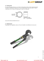
Inspection hole:
Copper strands visible
Electroustic Ltd www.electroustic.co.uk +44 (0)1908 307200


