Lapp Group EPIC POWERLOCK Скачать руководство пользователя страница 2


1. Overview 

Due to the wide range of cables used in the market, to ensure that a satisfactory result is 
obtained when EPIC

®

 POWERLOCK connectors are terminated onto the end of the cables, the 

type and method used needs to be evaluated. This guide is intended to provide details of how 
to successfully terminate cables into EPIC

®

 POWERLOCK connectors, either by crimping, set 

screws or threaded post methods.  This document provides guidelines on: 

• how to perform a crimped termination.


• what type of crimp tools and dies to use with recommendations.


• how to perform a set screw termination.


• terminating a threaded post panel type 

connector. 


2. Termination Methods 

EPIC

®

 POWERLOCK connectors can be terminated to cables by using one of the following 

methods: 

• Crimp termination.


• Set screw termination.


• Threaded post termination.


These recommended assembly methods are detailed below. If in doubt, consult Lapp. 
 

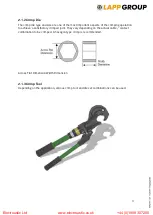
2.1 Crimp Termination 

It is essential to use the recommended crimp tool and die to ensure a satisfactory crimp.  It is 
important that you are satisfied that the crimped joint meets your requirements. Consult Lapp 
for more details. 
 

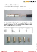
2.1.1 Crimp Connector Components  

Shown below are the components supplied for both EPIC

®

 POWERLOCK F6 drain and EPIC

®


POWERLOCK D6 source connectors. Both connector types include the following: 

• Cable Gland


• Contact


• Housing (Insulator)


• 

Retention Pin 


Electroustic Ltd                               www.electroustic.co.uk                       +44 (0)1908 307200

Содержание EPIC POWERLOCK

Страница 1: ...1 EPIC POWERLOCK Assembly instruction for Crimp and Set screw types Electroustic Ltd www electroustic co uk 44 0 1908 307200 L44420211EN 19 10 2016...

Страница 2: ...panel type connector 2 Termination Methods EPIC POWERLOCK connectors can be terminated to cables by using one of the following methods Crimp termination Set screw termination Threaded post termination...

Страница 3: ...factory crimped joint They vary depending on the actual cable contact combination to be crimped A hexagon type crimp is recommended Across Flat Dimension Width Dimension 2 1 3 Crimp Tool Depending on...

Страница 4: ...C 240 44420336 Crimpwerkzeug Crimp Die Type Description Crimp Die Details Die Across Flat Dimension mm Die Width Dimension mm C 130 44420330 44420331 44420332 44420333 44420334 44420335 44420336 C 25...

Страница 5: ...imping 120mm cables and smaller Each crimp should be positioned centrally within the contact crimp area The crimp area is between inspection hole and end of contact If a single crimp is used the crimp...

Страница 6: ...straight within a distance of 1 metre of the crimping location This ensures that the individual cable wire strands are not distorted or displaced to each other caused by bending the cable With the cr...

Страница 7: ...pin tapered end first into the insulator contact using either a press or a soft hammer Note that the Retention pin should only be used once Re using the Retention pin will invalidate the IP67 rating 9...

Страница 8: ...torques to ensure a satisfactory termination 2 2 1 Screw Connector Components Show below are the components supplied for both line drain and line source connectors Both connector types include the fol...

Страница 9: ...ctor stranding All sleeves down to the size recommended for the cable in use should be used i e for the 50m2 cable the R120 R95 R70 and R50 sleeves should all be used The sleeves fit inside each other...

Страница 10: ...tor and visually align the Retention pin holes 7 Fit the Retention pin tapered end first into the insulator contact using either a press or a soft hammer Note that the Retention pin should only be use...

Страница 11: ...r users of fine stranded cables When using fine stranded power cables it is advisable to use the maximum number of sleeves and increase the torque setting This will protect the individual cable strand...

Страница 12: ...2 Recommended Assembly Procedure 1 Fit the contact into the front insulator and visually align the Retention pin holes 2 Fit the Retention pin tapered end first into the insulator contact using eithe...

Страница 13: ...13 U I Lapp GmbH D 70565 Stuttgart Germany www lappgroup com A company of the Lapp Group Electroustic Ltd www electroustic co uk 44 0 1908 307200...

Отзывы: