2: Overview
SLC™ Console Manager User Guide
26
Hardware Features
The SLC hardware includes the following:
1U-tall (1.75 inches) rack-mountable secure console server
Two 10Base-T/100Base-TX network ports
Up to 48 RS-232 serial device ports connected via Category 5 (RJ45) wiring
One serial console port for VT100 terminal or PC with emulation
Two PC Card slots or one USB port
256 Kbytes-per-port buffer memory for device ports
LCD display and keypad on the front
Universal AC power input (100-240V, 50/60 Hz); options include single input, single supply or
dual input, redundant supplies
-48 VDC power input, dual input, redundant power supplies
Convection cooled, silent operation, low power consumption
Note:
For more detailed information, see
Technical Specifications on page 30.
All physical connections use industry-standard cabling and connectors. The network and serial
ports are on the rear panel of the SLC console manager, and the console port is on the front.
Required cables and adapters for certain servers, switches, and other products are available from
Lantronix at
.
Serial Connections
All devices attached to the device ports and the console port must support the RS-232C (EIA-232)
standard. Category 5 cabling with RJ45 connections is used for the device port connections and
for the console port. For pinout information, see
Appendix E: Adapters and Pinouts
.
Note:
RJ45 to DB9/DB25 adapters are available from Lantronix.
Device ports and the console port support eight baud-rate options: 300, 600, 1200, 2400, 4800,
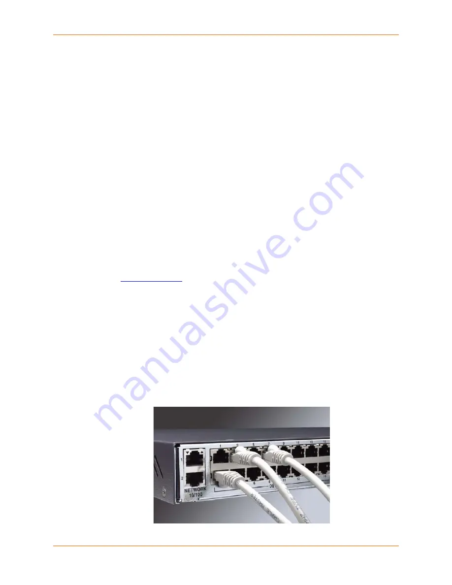
9600, 19200, 38400, 57600, and 115200 baud. The ports are shown in
.
Figure 2-4 Device Port Connections
Содержание SLC16
Страница 1: ...Part Number 900 449 Revision J July 2014 SLC Console Manager User Guide SLC8 SLC16 SLC32 SLC48 ...
Страница 95: ...8 Device Ports SLC Console Manager User Guide 95 Figure 8 4 Device Ports Settings ...
Страница 150: ...10 USB Port SLC Console Manager User Guide 150 Figure 10 3 Devices USB Modem 3 Enter the following fields ...
Страница 217: ...13 Maintenance SLC Console Manager User Guide 217 Figure 13 1 Maintenance Firmware Config ...


