2: Description and Specifications
MatchPort b/g Pro Integration Guide
17
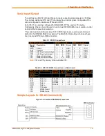
Figure 2-11. BOOTP_EN# APPLICATION CIRCUIT
Electrical Specifications
Caution:
Stressing the device above the rating listed in this table may cause
permanent damage to the MatchPort b/g Pro. Exposure to Absolute Maximum
Rating conditions for extended periods may affect the MatchPort b/g Pro's
reliability.
Table 2-3. Absolute Maximum Ratings
Parameter
Symbol
Min
Max
Units
Supply Voltage
V
CC
3.135
3.6
Vdc
CP Voltage
V
CP
-0.3
V
CC
+0.05
Vdc
Ethernet ETX+, ETX-, ERX+, ERX-
Voltage
V
ETH
0
V
CC
+0.3
Vdc
Operating Temperature
-40
70
o
C
Storage Temperature
-40
85
o
C
Table 2-4. Recommended Operating Conditions
Parameter
Symbol Min
Typical Max Units
Supply Voltage
V
CC
3.135 3.3
3.45
Vdc
Supply Voltage Ripples
V
CC_PP
2
%
Supply Current _ Power Management
enabled
I
CC
245
mA
Supply Current _ Power Management
disabled
260
mA
Supply Current (Peak)
350
mA
Supply Reset Threshold
V
RST
2.85
2.93
3.00
Vdc
CP Pull-ups, except CP5
R
PU
100
Kohm
CP5 Pull-up
R
PU
20
Kohm
CP, RX, CTS, BOOTP_EN#
Input Low Voltage
V
CP_IL
0.8
Vdc
CP, RX, CTS, BOOTP_EN#
Input High Voltage
V
CP_IH
2
Vdc
(see note below)
CP, TX, RTS Output Low Voltage
(I
OL
= 4 mA)
V
CP_OL
0.4
Vdc
CP, TX, RTS Output High Voltage
(I
OH
= -4 mA)
V
CP_OH
V
CC
-
0.4
Vdc
(see note below)
Содержание MatchPort b/g Pro
Страница 1: ...Part Number 900 532 Revision B December 2011 MatchPort b g Pro Integration Guide...
Страница 29: ...3 Demonstration Kit MatchPort b g Pro Integration Guide 29 Figure 3 3 Schematic...
Страница 30: ...3 Demonstration Kit MatchPort b g Pro Integration Guide 30 Figure 3 3 Schematic continued...
Страница 31: ...3 Demonstration Kit MatchPort b g Pro Integration Guide 31 Figure 3 3 Schematic continued...


