2: Description and Specifications
MatchPort b/g Pro Integration Guide
13
Serial Input/Output
The unit has two
RS232 compatible
serial ports supporting data rates up to 230 Kbps.
They include dedicated RTS and CTS hardware flow control signals. Configurable Pins
can be configured to function as DTR and/or DCD.
Serial Port 1 can also be configured for RS422/485. RTS is used as TX enable.
Configurable Pins can be configured to function as RS232/RS485 driver selection control
and/or half/full duplex driver selection.
The serial module interface employs 3.3V CMOS logic levels, requiring external level
shifters for full RS232/485/422 compliance The MatchPort Demo Board includes these
line drivers and DTE style DB9 connectors.
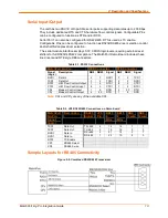
Table 2-1. RS232 Connections
MatchPort b/g Pro
DCE Connector
DTE Connector
Signal
(Logic)
Description
DB9 DB25 Signal
DB9 DB25 Signal
RXD1
Data In
2
3
RXD1
3
2
TXD1
TXD1
Data Out
3
2
TXD1
2
3
RXD1
RTS1
H/W Flow Control Output
7
4
RTS1
8
5
CTS1
CTS1
H/W Flow Control Input
8
5
CTS1
7
4
RTS1
CPx
Modem Control Input
1
8
DCD
4
20
DTR
CPy
Modem Control Output
4
20
DTR
1
8
DCD
Note:
CPx and CPy are any of the available CPs.
Table 2-2. JP6 RS422/485 Connections on Demo board
MatchPort
b/g Pro
Signal
(logic)
Description
RS485
Signal
JP6
Pin
DB25
4
Wire
DB25
2
Wire
DB9
4 wire
DB9
2 wire
TXD1
Data Out
TX+485
4
14
14
7
7
TXD1
Data Out
TX-485
3
15
15
3
3
RXD1
Data In
RX+485
2
21
14
2
7
RXD1
Data In
RX-485
1
22
15
8
3
RTS1
TX Enable
CP3
RS485 Select
CP4
RS485 2-wire
Sample Layouts for RS485 Connectivity
Figure 2-8. Combined RS232/422 Transceiver
Содержание MatchPort b/g Pro
Страница 1: ...Part Number 900 532 Revision B December 2011 MatchPort b g Pro Integration Guide...
Страница 29: ...3 Demonstration Kit MatchPort b g Pro Integration Guide 29 Figure 3 3 Schematic...
Страница 30: ...3 Demonstration Kit MatchPort b g Pro Integration Guide 30 Figure 3 3 Schematic continued...
Страница 31: ...3 Demonstration Kit MatchPort b g Pro Integration Guide 31 Figure 3 3 Schematic continued...


