Section 1: Assembly & Set-up
11/2/18
16
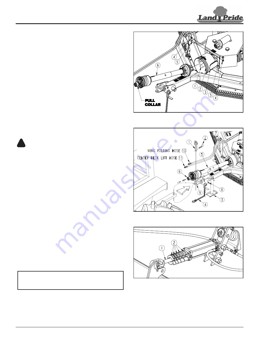
Refer to power take-off Figure 1-7:
1.
Remove shaft protector (#1) from splitter gearbox
input shaft.
2. Unsnap doors (#3) and remove bolts (#5) from yoke
end of driveline (#6). Slide that yoke onto the gearbox
input shaft.
3. Align holes in driveline yoke with groove around
gearbox input shaft and insert removed bolts (#5)
through yoke end of driveline as shown.
4. Secure bolts (#5) with hex flange locknuts (#4).
Tighten locknuts to the correct torque.
5. Pull back on the pull collar and push driveline yoke
onto the tractor power take-off shaft. Release pull
collar and continue to push driveline yoke forward
until pull collar locks in place.
6. The driveline should now be moved back and forth to
ensure both ends are secured to the tractor and
cutter. Reattach any end that is loose.
Driveline Hook-up to Tractor
DANGER
!
To avoid serious injury or death:
Do not use a power take-off adapter. The adapter will increase
strain on the tractor’s power take-off shaft causing possible
damage to shaft and driveline. It will also defeat the purpose
of the tractor’s power take-off shield.
1.
If needed, collapse driveline (#5) by pushing tractor
end of driveline toward the splitter gearbox.
2. Pull back on outer yoke locking collar (#6) and slide
outer yoke onto the tractor power take-off shaft.
3. Release locking collar and continue to push outer
yoke onto the power take-off shaft until locking collar
snaps in place.
4. Driveline (#5) should now be moved back and forth to
ensure both ends are secured to the tractor and
cutter. Reattach any end that is loose.
5. If park jack (#3) is attached to the hitch, it should be
removed and stored on the left-hand wing. For
detailed instructions, see steps 9 & 10 on page 14.
Driveline Clearance Check
Check driveline for adequate clearance under all ranges
of cutter height.
1.
Fully extend center deck lift cylinder with tractor
control lever. Place gear selector in park, shut tractor
engine off, set park brake, and remove switch key.
NOTE:
The lift cylinder should raise cutter up while
pushing tractor control lever forward. Switch duplex
connections if lift control lever works opposite.
Driveline Installation
Figure 1-7
Tractor Hookup
Figure 1-8
Remove Stroke Control Spacers
Figure 1-9
2. Remove all stroke control spacers (#3) from deck lift
cylinder rod.
3. Slowly retract and extend center deck lift cylinder to
its most upper and lower limits while observing
clearances between hitch and driveline.
35964
35244
35134


