Section 1: Assembly & Setup
AFM4522 All-Flex Grooming Mower 315-360M
11/18/21
20
Install Drivelines
DANGER
!
To avoid serious injury or death:
•
All guards and shields must be installed and in good
working condition while operating the implement.
•
Do not use a power take-off adapter. The adapter will
increase strain on the tractor’s power take-off shaft causing
possible damage to shaft and driveline. It will also defeat
the purpose of the tractor’s power take-off shield.
WARNING
!
To avoid serious injury or death:
•
Always follow “Tractor Shutdown Procedure” provided in
this manual before dismounting the tractor.
•
Do not operate a broken or bent driveline. Such a driveline
will break apart while rotating at high speeds. Always
remove the implement from use until the damaged driveline
•
Some tractors are equipped with two power take-off speeds.
Be certain your tractor’s power take-off shaft is set-up to
operate at 540 rpm. Do not exceed 540 rpm power take-off
speed. Excessive speed can damage drive components,
cutter blades, and/or increase the risk of a thrown object
Always engage power take-off at low engine rpm to
minimize start-up torque on driveline.
Drivelines with
friction clutches must go through a “run-in”
operation prior to initial use and after long periods of
inactivity
on page 40 for a
detailed run-in description.
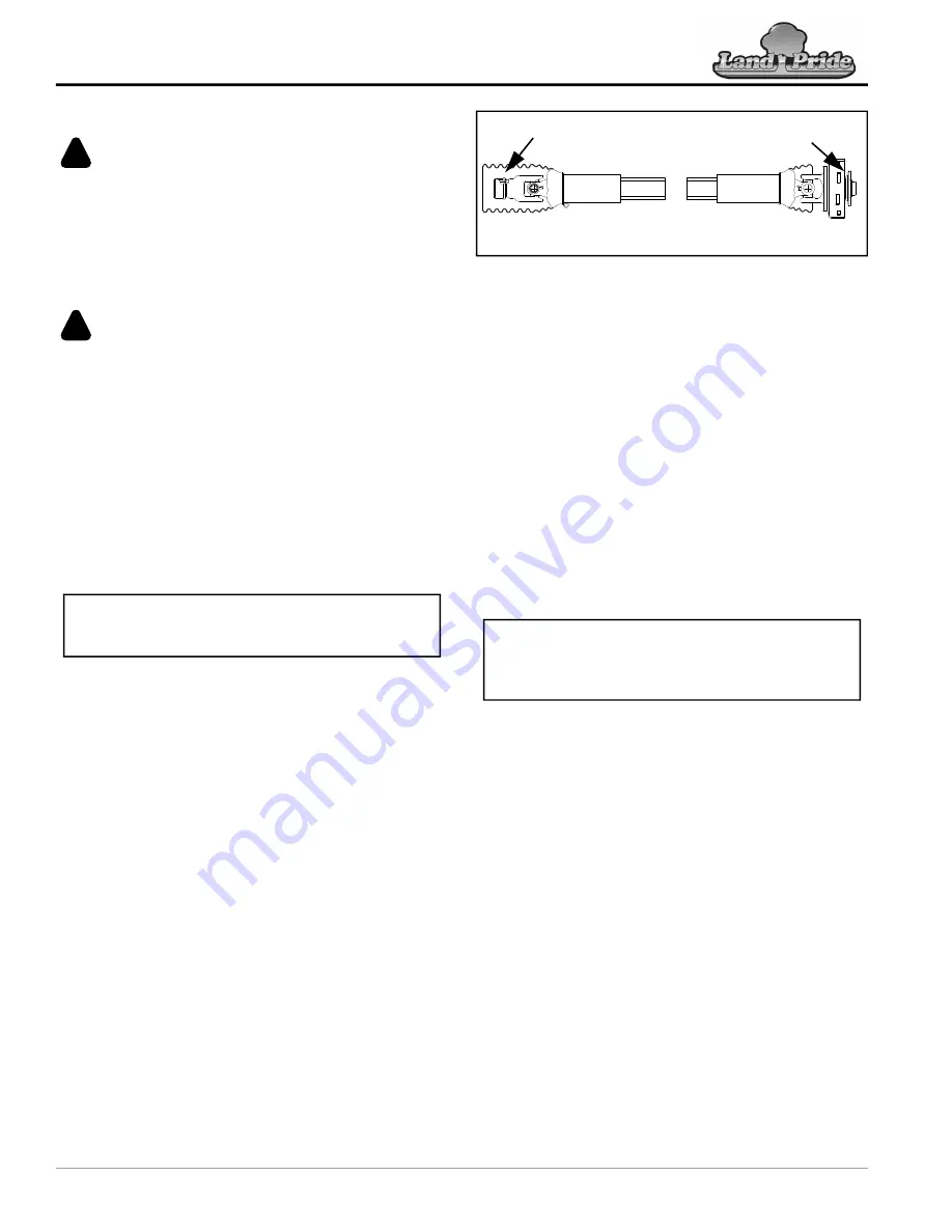
Deck Drivelines
Refer to Figure 1-10:
There are three deck drivelines with slip clutches. The
slip clutch end attaches to the splitter gearbox. The
center driveline is shorter than the other two drivelines.
1. Shutdown tractor before dismounting. Refer to
2. Pull all three deck driveline profiles apart.
3. Apply multi-purpose grease to the inside of the outer
profile and reassemble the two profiles.
4. Attach center driveline to the splitter gearbox output
shaft as follows:
a. Pull back on the slip clutch lock collar and slide
yoke end of slip clutch over the splitter gearbox
center output shaft.
b. Release lock collar and continue to push yoke end
onto the shaft until pull collar snaps in place.
IMPORTANT:
The driveline must be lubricated
before putting it into service. Refer to
Deck Drivelines
Figure 1-10
5. Attach center driveline to the center deck gearbox
input shaft as follows:
a. Pull back on spindle gearbox lock collar and slide
yoke end over the spindle gearbox input shaft.
b. Release lock collar and continue to push yoke end
onto the shaft until pull collar snaps in place.
c. If driveline does not fits between splitter gearbox
on page 21. Otherwise,
continue with step 6.
6. Move driveline back and forth to ensure both ends
are secured. Reattach any end that is loose.
7.
Repeat steps 4-6 for the left-hand deck driveline.
8. Repeat steps 4-6 for the right-hand deck driveline.
Main Driveline
Refer to Figure 1-11 on page 21:
1. If driveline collapsible length has not been checked,
go to
“Check Driveline Collapsible Length”
page 21. Otherwise, continue with step 2 below.
2. Place tractor gear selector in park, shut tractor
engine off, set park brake, and remove switch key.
3. Pull main driveline profiles apart, apply multi-
purpose grease to the inside of the outer profile and
reassemble the two profiles.
4. If needed, attach driveline to the gearbox input shaft:
a. Pull back on inner driveline yoke lock collar and
slide yoke over the splitter gearbox input shaft.
b. Release lock collar and continue to push yoke
onto the input shaft until pull collar snaps in place.
5. Attach driveline to the tractor’s power take-off shaft:
a. Pull back on outer driveline yoke lock collar and
slide yoke over the tractor’s power take-off shaft.
b. Release lock collar and continue to push yoke
onto the shaft until pull collar snaps in place.
c. Move driveline back and forth to ensure both ends
are secured. Reattach any end that is loose.
12729
Splitter Gearbox End
With Slip Clutch
Spindle Gearbox End
Lock Collar
Lock Collar
IMPORTANT:
Always check driveline length during
initial setup and when connecting to a different


