manualshive.com logo in svg
background image

15

Every Six Months

• 

Clean the syrup lines as specified by the section “Cleaning and Sanitizing Syrup Lines - Bag in Box” on 

page 16.

•  Pull out unit (if applicable) and clean behind and underneath. Check for any loose components or 

noises.

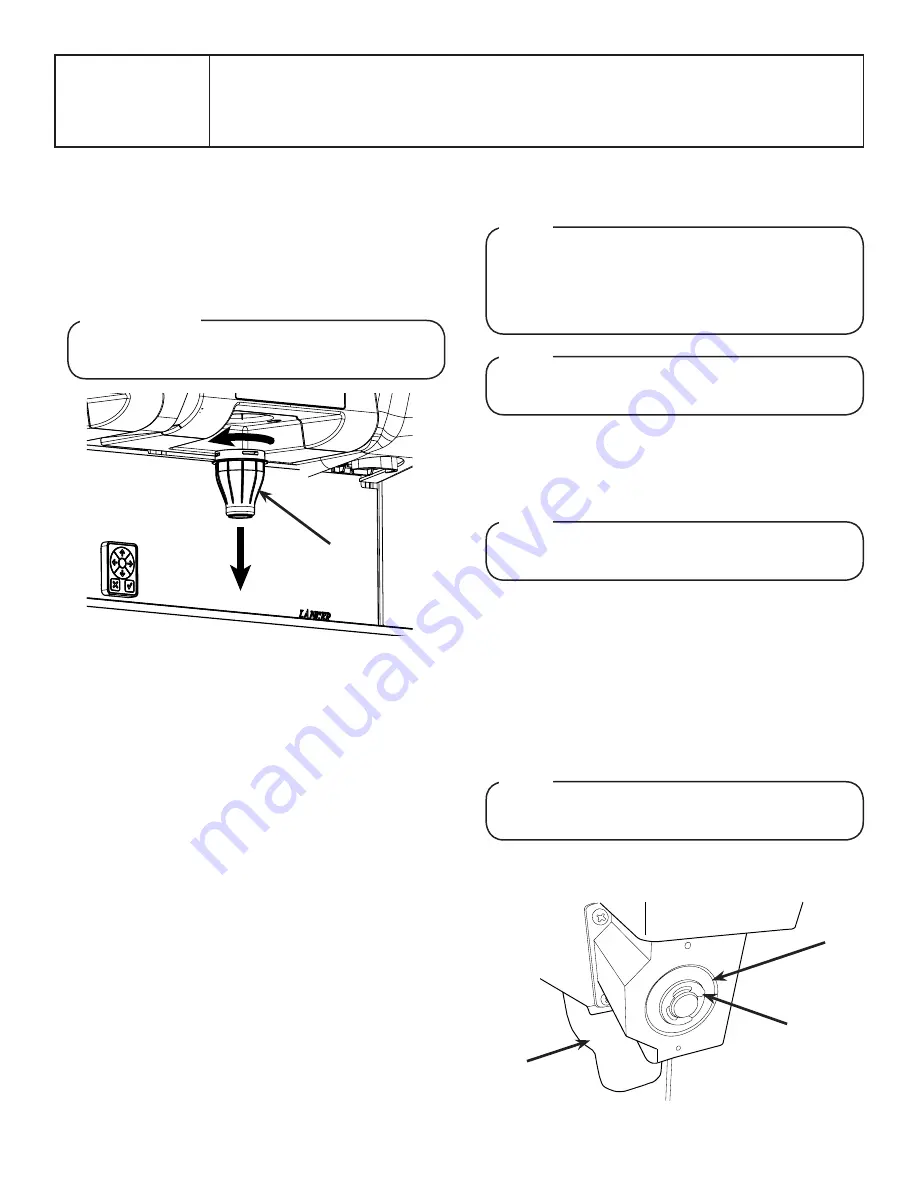
Cleaning & Sanitizing Nozzles

1.  Prepare the nozzle sanitizing solution as described on the 

previous page. 

2.  Turn the left and right key switches to deactivate valves and 

avoid accidental dispense while the nozzles are exposed.

3.  Remove the outer nozzle by twisting clockwise and pulling 

downward.  


DO NOT

 attempt to activate any valves while the outer 

nozzle is removed.

ATTENTION

A

A. Nozzle

4.  Using the nozzle brush provided in the installation kit and the 

cleaning solution described on page 18, clean the outer 

nozzle of any residual syrup.

5.  Rinse the outer nozzle with clean, potable water then soak in 

the nozzle sanitizing solution prepared in step 1.

6.  While the outer nozzle is in the sanitizing solution, using the 

nozzle brush, dip the brush in the nozzle sanitizing solution 

and thoroughly brush the bottom of the inner nozzle body.

7.  Rinse the brush in warm 90° – 110°F (32.2°– 43.3°C), clean 

potable water and brush the bottom of the inner nozzle body 

once more 

WITHOUT

 the sanitizing solution.

8. 

After the outer nozzle has soaked for fifteen (15) minutes, 

rinse in warm 90° – 110°F (32.2°– 43.3°C), clean potable 

water for a minimum of twenty (20) seconds ensuring all 

surfaces of the nozzle have been thoroughly rinsed.

9.  Allow outer nozzle to air dry (to expedite drying, forced  

convection is recommended).

10.  Reinstall the outer nozzle to the unit.
11. 

Repeat Steps 3 - 10 for the second nozzle.

12.  Return the left and right key switches to active valves.

Cleaning & Sanitizing Ice Bin, Auger, and  
Ice Chute

1.  Disconnect power to the dispenser
2.  Remove the Merchandiser and Top Cover.
3.  Remove Ice Chute Lever, then remove Splash Plate          

Assembly by lifting it up and out from the dispenser face.


Refer to the Automatic Agitation Warning on the first 


page of this manual.

NOTE


It is recommended to perform this procedure monthly, 


or more often if desired. Use the cleaning solution 


described on page 14. An alternate solution of one part 


water to one part vinegar may be used to remove 


water spots and calcium deposits.

NOTE


Always remove the ice chute lever before removing the 


splash plate.

NOTE

4.  Remove or melt out any remaining ice from the ice bin.
5.  Disconnect the two (2) lower, horizontal LED light bars and 

remove from unit.

6. 

Disconnect vertical LED light bar, next to flavor injector 


nozzle, from the junction box and remove from unit. 

7.  Repeat previous step for second light bar on opposite side of 

the unit.

8. 

Rotate the flavor injector nozzle 90° to disconnect from 

bracket.


DO NOT

 disconnect flavor lines from nozzle, when 


removing from bracket.

NOTE

A

B

C

A. Auger Motor Shaft

B. “C” Clip

C. Ice Chute

9.  Use a screwdriver to remove the Auger Motor shaft cover.
10.  Remove the “C” clip from the Auger Motor Shaft.

Содержание Twin Pour

Страница 1: ...ss or for your convenience scan this QR code with a mobile device app required for immediate access to other Technical Documents and alternative translations if available pertaining to this unit Conta...

Страница 2: ...ing 585 lbs 265 kg Operating w Ice 745 lbs 338 kg Ice Capacity 312 lbs 142 kg CARBON DIOXIDE CO2 SUPPLY Min Pressure 70 psi 0 483 MPa Max Pressure 80 psi 0 552 MPa FITTINGS Carbonator Inlet 3 8 inch b...

Страница 3: ...re that the dispenser is level front to back and side to side Place a level on the top of the rear edge of the dispenser The bubble must settle between the level lines Repeat this procedure for the re...

Страница 4: ...n a counterclockwise direction up to a 45 angle 4 Carefully pull ADA panel and electric wire harness from the unit s splash plate until the harness connector is visible 5 Disconnect ADA harness and re...

Страница 5: ...Tube to become clogged with coffee or tea grounds or other solid particles ATTENTION 16 Reattach Drip Tray and Cup Rest to unit if applicable When installing the drip tray make sure both of the cold p...

Страница 6: ...nut on the regulator adjustment screw of the high pressure CO2 regulator connected to the source then using a screwdriver back out lock nut screw all the way DO NOT TURN ON CO2 SUPPLY AT THIS TIME WA...

Страница 7: ...d right screen by pressing the screen on off toggle buttons on the left side of the unit electrical box The manager s access to the service menu allows access to the Lighting screen see page 12 the So...

Страница 8: ...flipping the switch on the control box NOTE To check for CO2 leaks close the valve on the CO2 cylinder and observe if the pressure to the system drops with the cylinder valve closed for five minutes O...

Страница 9: ...Repeat Steps 4 and 5 for any of the other brand or flavor modules 8 Press the Menu button to return to the Service menu 12 Press the Menu button to return to the Service Menu 13 Repeat steps 1 12 for...

Страница 10: ...m on page 17 for reference 1 From the Service menu press the Maintenance button 2 Remove the two thumb screws connecting the plastic screen housing to the unit See page 9 3 While holding the plastic s...

Страница 11: ...9 for the remaining brand syrup modules 11 To re attach the screen housing first align the screen housing with the connection tabs on the unit then rotate the housing down untill the connection tabs...

Страница 12: ...sing down untill the connection tabs engage 13 Re connect the two thumb screws removed in Step 2 14 Repeat steps 1 13 for the second screen Make sure both of the connection tabs are disengaged in the...

Страница 13: ...problem with the specified brand and will dispense when activated Auto signifies that the configured Sold Out Sensor controls whether the brand can be dispensed This feature requires an optional sold...

Страница 14: ...ble water at a temperature of 90 F to 110 F Extended lengths of product lines may require additional cleaning solution Sanitizing Solution Prepare the sanitizing solution in accordance with the manufa...

Страница 15: ...twenty 20 seconds ensuring all surfaces of the nozzle have been thoroughly rinsed 9 Allow outer nozzle to air dry to expedite drying forced convection is recommended 10 Reinstall the outer nozzle to t...

Страница 16: ...ll interior surfaces of the ice chute and the ice chute feed through 29 Wearing sanitary gloves reassemble all removable parts Ensure agitator clip is locked 30 Fill unit with ice and replace Top Cove...

Страница 17: ...ement Residual sanitizing solution left in the system creates a health hazard CAUTION 7 Flush out cleaning solution from the flavor injector lines using clean warm water 8 Prepare Sanitizing Solution...

Страница 18: ...ED 3 5a C B 3 5a C B 7A C B CONTROL PCB R CONTROL PCB L ICE SOLE ICE SOLE TRIGGER TRIGGER 12VDC 12VDC 24VDC 24VDC 24VDC 115VAC 24VDC 24VDC HDMI HDMI USB USB USB USB CTRL PCB CTRL PCB LEFT SIDE VALVES...

Страница 19: ...Blk Red WHT N N N L N G V V V V GRN WHT BLK WHT BLK GRN GRN BLK WHT RED BLK RED WHT BLK WHT BLK BLK WHT WHT BLK BLK RED RED BLK GRN WHT BLK POWER SUPPLY AND IBD CONTROLLER BOX 2 to 1 adapter RIGHT RI...

Страница 20: ...6 7 6 2 2 3 8 3 4 7 4 5 SW1 SWITCH 1 NOT USED FOR MODEL 4900 ON 5 4 SWITCH AGITATOR ON TIME 5 6 OFF OFF 11 SECONDS OFF ON 9 SECONDS ON OFF 7 SECONDS ON ON 5 SECONDS SWITCH AUGER RUN TIME 7 8 OFF OFF 6...

Отзывы: