5
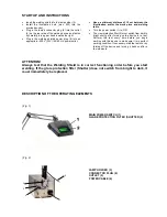
Illus. 3)
12
13
14
15
4-4. STARTING UP
•
Set up the device on a level and stable as well as
insulated surface, such as a workbench.
•
Insert the hand piece connector as straight as possible
into the jack
(5)
and carefully turn per hand towards the
right to secure.
•
Insert the connector of the clamp or pliers into one of
the jacks
(6)
.
•
Unscrew the valve
(12)
of the hand piece
(15)
•
Loosen the electrode thread
(14)
, insert the newly
sharpened tungsten electrode
(13)
and screw on tightly
(per hand - do not use a wrench) with the electrode
projecting ca. 5 – 8 mm out of the valve (illus. 3).
(Use original electrodes only)
•
Screw the valve back on (per hand do not use a
wrench)
•
Fasten the welding shield with the provided table
clamp onto the workbench.
•
Insert the round connector of the shutter into the with
„filter“ indicated connector jack
(11)
on the rear side of
the device and secure with the grub screws.
•
Attach the pressure gauge onto the inert gas bottle (if
possible use Argon with min. 99.8%, i.e. „Argon 4.6“)
according to the provided operations manual.
•
Attach the pressure hose with help of the fast screws
onto the pressure gauge as well as onto the gas
connector
(10)
on the rear side of the device.
•
Open the gas bottle valve and set the gas flow to ca. 3
– 6 liter per minute –
m a x i m u m operating
pressure 10 bar!
•
Insert the power plug.
•
Switch the mains power switch
(8)
to „ON“ – the device
will perform an automatic test.
•
The
yellow
control
light
(2)
will glow when the device is
ready for operation.
•
Choose the power on the weld power deal with the
level switch
(3)
.
•
The pulse length can be changed with the switch
(4)
i.e. to smooth out welding spots or to change the depth
of penetration.
•
Always use appropriate eye protection.
Follow the operations instructions of the attached
eye protection devices such as welding shield or
Microscope Shutter!
ATTENTION!
Clamps or pliers, which are attached to the OPTI-WELDER T1, could be conducting voltage, as soon as
the power mains switch is turned on. Make sure that these components do not touch any electrical
conducting parts such as the casing.
SECTION 5 – INSTRUCTIONS
5-1. WELDING INSTRUCTIONS
•
Connect the clamp to piece to a blank metal location
on the work piece.
•
Make sure the clamp has sufficient contact.
•
Touch the electrode tip to the spot to be welded until
the welding is done
--- without, or with minimum
pressure to the electrode tip!
•
The welding procedure is automatically done:
o
Safety gas encases the welding spot
o
A signal announces the arc
o
The light arc appears
o
Safety gas supply ceases
•
The welding procedure may be stopped anytime by
removing the electrode from the work piece.
Содержание optiwelder T1
Страница 11: ...10...


