background image

AXE 3 D UNIT 32 R HR

15

EN

cod. 3541B310  -  10/2011  (Rev. 00)

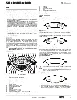
Service Menu

The card is equipped with two Menus: one for configuration and the other defined Serv-
ice.
The configuration Menu is accessed by pressing the DHW buttons together for 10 sec-
onds. Only one parameter modifiable only from card for security reasons is available.

To exit the configuration Menu, press the DHW buttons together for 10 seconds.
The card Service Menu is accessed by pressing the Reset button for 10 seconds. Press
the Heating buttons to select "tS", "In", "Hi" or "rE". "tS" means Transparent Parameters
Menu, "In" Information Menu, "Hi" History Menu, and "rE" History Menu Reset. After se-
lecting the Menu, press the Reset button to access it.

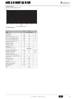
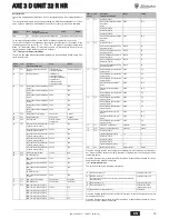
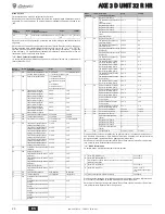
"tS" - Transparent Parameters Menu

The card is equipped with 20 transparent parameters also modifiable from Remote Con-
trol (Service Menu):

Press the Heating buttons to scroll the list of parameters in increasing or decreasing or-
der. Press the DHW buttons to modify the value of a parameter: the change will be au-
tomatically saved.
Press the Reset button to return to the Service Menu. Press the Reset button for 10 sec-
onds to exit to the card Service Menu.

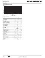
"In" - Information Menu

The card can display the following information:

Press the Heating buttons to scroll the list of information. In case of damaged sensor, the
card displays hyphens.
Press the Reset button to return to the Service Menu. Press the Reset button for 10 sec-
onds to exit to the card Service Menu.

Remote
Control

Card

Description
Transparent Parameters

Range

Default

NO

P01

External or internal flame control selection

0=External, 1=Internal 0=External

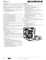
Remote
Control

Card

Description
Transparent Parameters

Range

Default

01

P01

System water pressure protection 
selection

0=Pressure switch, 
1=Pressure transducer

1=Pressure transducer

02

P02

Boiler type selection

1=Heating only
2=Storage with probe
3=Storage with thermostat
4=Instantaneous
5=Bithermal instant.
6=Storage with probe

1

03

P03

Heating pump activation temperature 
(P02=1)

0-80°C

30°C

Heating pump activation temperature 
(P02=2)

0-80°C

30°C

Heating pump activation temperature 
(P02=3)

0-80°C

30°C

Heating pump activation temperature 
(P02=4)

0-80°C

30°C

Heating pump activation temperature 
(P02=5)

0-80°C

30°C

Heating pump activation temperature 
(P02=6)

0-80°C

30°C

04

P04

Heating pump Post-Circulation

0-20 minutes

6 minutes

05

P05

Heating standby time

0-10 minutes

2 minutes

06

P06

Pump operation

0=Post-Circulation
1=Continuous

0=Post-Circulation

07

P07

Pump deactivation temperature dur-
ing Post-Circulation (P02=1)

0-100°C

35°C

Pump deactivation temperature dur-
ing Post-Circulation (P02=2)

0-100°C

35°C

Pump deactivation temperature dur-
ing Post-Circulation (P02=3)

0-100°C

35°C

Pump deactivation temperature dur-
ing Post-Circulation (P02=4)

0-100°C

35°C

Pump deactivation temperature dur-
ing Post-Circulation (P02=5)

0-100°C

35°C

Pump deactivation temperature dur-
ing Post-Circulation (P02=6)

0-100°C

35°C

08

P08

Heating user max. set point

31-90°C

80°C

09

P09

No function (P02=1)

--

--

DHW pump activation temperature 
(P02=2)

0-80°C

40°C

DHW pump activation temperature 
(P02=3)

0-80°C

40°C

DHW pump activation temperature 
(P02=4)

0-80°C

40°C

No function (P02=5)

--

--

DHW pump activation temperature 
(P02=6)

0-80°C

40°C

10

P10

DHW pump Post-Circulation

0-255 seconds

30 seconds

11

P11

DHW standby time

0-255 seconds

120 seconds

12

P12

DHW user max. set point (P02=1)

--

--

DHW user max. set point (P02=2)

55-65°C

65°C

DHW user max. set point (P02=3)

--

--

DHW user max. set point (P02=4)

--

--

DHW user max. set point (P02=5)

--

--

DHW user max. set point (P02=6)

55-65°C

65°C

13

P13

No function (P02=1)

--

--

Hot water tank activation hysteresis 
temperature
(P02=2)

0-20°C

40°C

No function (P02=3)

--

--

No function (P02=4)

--

--

No function (P02=5)

--

--

Hot water tank activation hysteresis 
temperature
(P02=6)

0-20°C

40°C

14

P14

No function (P02=1)

--

--

Hot water tank preparation delivery 
temperature (P02=2)

70-85°C

80

Hot water tank preparation delivery 
temperature (P02=3)

70-85°C

80

Delivery temperature adjustment in 
DHW mode (P02=4)

50-65°C

55

Delivery temperature adjustment in 
DHW mode (P02=5)

50-65°C

55

Hot water tank preparation delivery 
temperature (P02=6)

70-85°C

80

15

P15

Boiler shell Warm-up activation tem-
perature (P02=1)

0-80°C

0°C

Boiler shell Warm-up activation tem-
perature (P02=2)

0-80°C

0°C

Boiler shell Warm-up activation tem-
perature (P02=3)

0-80°C

0°C

Comfort activation temperature 
(P02=4)

0-80°C

55°C

Comfort activation temperature 
(P02=5)

0-80°C

55°C

Boiler shell Warm-up activation tem-
perature (P02=6)

0-80°C

0°C

16

P16

Boiler shell Warm-up deactivation 
hysteresis (P02=1)

0-20°C

5°C

Boiler shell Warm-up deactivation 
hysteresis (P02=2)

0-20°C

5°C

Boiler shell Warm-up deactivation 
hysteresis (P02=3)

0-20°C

5°C

Comfort deactivation hysteresis 
(P02=4)

0-20°C

20°C

Comfort deactivation hysteresis 
(P02=5)

0-20°C

20°C

Boiler shell Warm-up deactivation 
hysteresis (P02=6)

0-20°C

5°C

17

P17

System min. pressure value

0-8 bar/10

2 bar/10

18

P18

System nominal pressure value

5-20 bar/10

6 bar/10

19

P19

No function (P02=1)

--

--

Legionella protection (P02=2)

0-7

0

No function (P02=3)

--

--

No function (P02=4)

--

--

No function (P02=5)

--

--

Legionella protection (P02=6)

0-7

0

20

P20

Mains Voltage Frequency

0=50Hz,1=60Hz

0=50Hz

t1

NTC Heating sensor (°C)

between 05 and 125°C

t2

NTC DHW sensor (°C)
(Only with Parameter P02=2, boiler with storage or with Parameter P02=6, 
boiler with storage)

between 05 and 125°C

t3

NTC Safety sensor (°C)

between 05 and 125°C

t4

NTC External sensor (°C)

between -30 and 70°C
(Negative values flash)

P5 Actual system water pressure (bar/10)

00-99 bar/10

Remote
Control

Card

Description
Transparent Parameters

Range

Default

Содержание AXE 3 D UNIT 32 R HR

Страница 1: ...ER L USO L INSTALLAZIONE E LA MANUTENZIONE EN INSTRUCTIONS FOR USE INSTALLATION AND MAINTENANCE ES INSTRUCCIONES DE USO INSTALACI N Y MANTENIMIENTO FR INSTRUCTIONS D UTILISATION D INSTALLATION ET D EN...

Страница 2: ...nto impostazione temperatura impianto riscaldamento 4 Tasto incremento impostazione temperatura impianto riscaldamento 5 Display 6 Tasto selezione modalit Estate Inverno 7 Tasto selezione modalit Econ...

Страница 3: ...one caldaia lavora con Temperatura Scorrevole In questa modalit la temperatura dell impianto di riscaldamento viene regolata a seconda delle condizioni climatiche esterne in modo da garantire un eleva...

Страница 4: ...ad altri componenti e o materiali di caldaia ed impianto proibito l uso di liquidi antingelo additivi e inibitori generici non espressamente adatti all uso in impianti termici e compatibili con i mat...

Страница 5: ...rico evitando restrizioni ed occlusioni B IMPORTANTE Prima della messa in funzione dell apparecchio riempire il si fone d acqua Verificare periodicamente la presenza di acqua nel sifone fig 18 Scarico...

Страница 6: ...02 2 0 100 C 35 C Temperatura spegnimento pompa durante Post Circolazione P02 3 0 100 C 35 C Temperatura spegnimento pompa durante Post Circolazione P02 4 0 100 C 35 C Temperatura spegnimento pompa du...

Страница 7: ...funzioni correttamente Questo controllo va fatto con gli appositi strumenti seguendo le istruzioni del costruttore Verificare la corretta programmazione dei parametri ed eseguire le eventuali perso n...

Страница 8: ...errati Controllare Giunto motore pompa rotto Sostituire Aspirazione pompa collegata al tubo di ritorno Correggere collegamento Fotoresistenza difettosa Sostituire Fotoresistenza sporca Pulire foto res...

Страница 9: ...min 80 60 C 97 9 Rendimento Pmax 50 30 C 102 7 Rendimento Pmin 50 30 C 103 9 Rendimento 30 103 6 Classe efficienza direttiva 92 42 EEC Pressione max esercizio riscaldamento bar 3 PMS Pressione min ese...

Страница 10: ...vie 2 fili con ritorno a molla non fornita 138 Sonda esterna opzionale 139 Unit ambiente opzionale 246 Trasduttore di pressione 278 Sensore doppio Sicurezza riscaldamento TR Trasformatore d accensione...

Страница 11: ...increase button 3 Heating system temperature setting decrease button 4 Heating system temperature setting increase button 5 Display 6 Summer Winter mode selection button 7 Economy Comfort mode select...

Страница 12: ...ntrol system works with Sliding Temperature In this mode the heating system temperature is controlled according to the outside weather conditions in order to ensure high comfort and energy saving thro...

Страница 13: ...to use generic antifreeze fluid additives or inhibitors that are not ex pressly suited for use in heating systems and compatible with the materials of the boiler unit and system Connection to a storag...

Страница 14: ...installed sloping at least 3 towards the drain with out any constrictions and occlusions B IMPORTANT Fill the trap with water before starting the unit Periodically check the water in the trap fig 18...

Страница 15: ...tion P02 3 0 100 C 35 C Pump deactivation temperature dur ing Post Circulation P02 4 0 100 C 35 C Pump deactivation temperature dur ing Post Circulation P02 5 0 100 C 35 C Pump deactivation temperatur...

Страница 16: ...fumebox and burner door Make sure the burner works properly This check must be made with the special in struments following the manufacturer s instructions Check correct programming of the parameters...

Страница 17: ...Replace and protect Faulty valve or transformer electrical con nections Check Broken pump motor joint Replace Pump inlet connected to return pipe Correct the connection Faulty photoresistance Replace...

Страница 18: ...97 1 Efficiency Pmin 80 60 C 97 9 Efficiency Pmax 50 30 C 102 7 Efficiency Pmin 50 30 C 103 9 Efficiency 30 103 6 Efficiency class Directive 92 42 EEC Max working pressure in heating bar 3 PMS Min wor...

Страница 19: ...ay valve 2 wires with spring return not supplied 138 External probe optional 139 Room unit optional 246 Pressure transducer 278 Double sensor Safety Heating TR Ignition transformer PR Preheater FR Pho...

Страница 20: ...8 Tecla de rearme reset 9 Tecla para encender apagar el aparato 10 Tecla men Temperatura adaptable 11 Indicaci n de que se ha alcanzado la temperatura programada del ACS 12 S mbolo de agua caliente sa...

Страница 21: ...laci n de la caldera funciona con Temperatura adaptable En esta modalidad la temperatura del circuito de calefac ci n se regula en funci n de las condiciones clim ticas exteriores con el fin de garant...

Страница 22: ...congelantes aditivos e inhi bidores gen ricos que no est n expresamente indicados para el uso en instalaciones t rmicas o sean incompatibles con los materiales de la caldera y de la instalaci n Conexi...

Страница 23: ...evitando estrechamientos y oclusiones B IMPORTANTE Antes de poner el equipo en marcha llenar el sif n de agua Verificar peri dicamente que haya agua en el sif n fig 18 Descarga de condensados 4 SERVI...

Страница 24: ...atura de apagado bomba durante postcirculaci n P02 3 0 100 C 35 C Temperatura de apagado bomba durante postcirculaci n P02 4 0 100 C 35 C Temperatura de apagado bomba durante postcirculaci n P02 5 0 1...

Страница 25: ...que el quemador funcione correctamente Este control debe efectuarse con los respectivos instrumentos y aplicando las instrucciones del fabricante Verificar la correcta programaci n de los par metros y...

Страница 26: ...correctas de v l vula o transformador Controlar Acoplamiento motor bomba roto Cambiar Aspiraci n de la bomba conectada al tubo de retorno Corregir la conexi n Fotorresistencia averiada Cambiar Fotorre...

Страница 27: ...Pm n 80 60 C 97 9 Rendimiento Pm x 50 30 C 102 7 Rendimiento Pm n 50 30 C 103 9 Rendimiento 30 103 6 Clase de eficiencia seg n directiva 92 42 CE Presi n m xima funcionamiento calefacci n bar 3 PMS Pr...

Страница 28: ...2 conductores con resorte de retorno no suministrada 138 Sonda exterior opcional 139 Unidad de ambiente opcional 246 Transductor de presi n 278 Sensor doble seguridad calefacci n TR Transformador de e...

Страница 29: ...irective 92 42 Low Voltage Directive Electromagnetic Compatibility Directive D claration de conformit Le constructeur d clare que cet appareil est conforme aux directives CEE ci dessous Directive rend...

Страница 30: ...ie de conformitate Produc tor declar c acest aparat este n conformitate cu urm toarele directive CEE Directiva Randament 92 42 Directiva Joas Tensiune Directiva Compatibilitate Electromagnetic CEE 92...

Страница 31: ......

Страница 32: ...52 EXPORT 0532 359947 Le illustrazioni e i dati riportati sono indicativi e non impegnano La LAMBORGHINI si riserva il diritto di apportare senza obbligo di preavviso tutte le modifiche che ritiene pi...

Отзывы: