55
ADJUSTMENTS
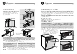
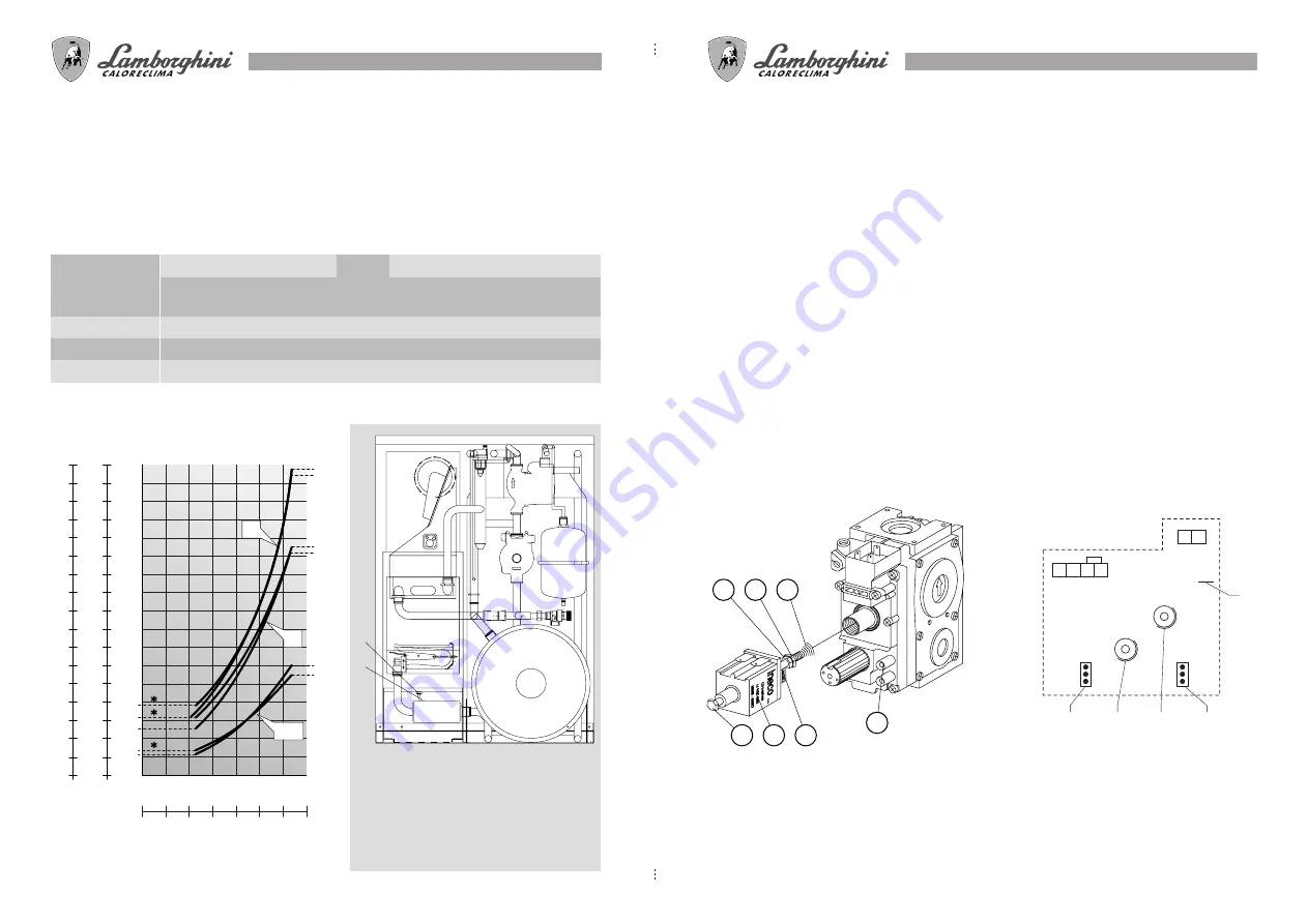
The boilers are equipped with fast-opening gas valves. By means of a double-adjusting modulating coil, the
required calibration of the gas flow rate may be obtained (min. 11,200 - max. 24,000 kcal/h).
The calibration for slow starting (pre-set at the factory) is electronic and adjustable (for optimum functioning
and the conversion of gas) by means of trimmer P2 (1) located on the modulation board. Turning trimmer
P1 (2) enables the regulation of the thermal power necessary for the heating system. All boilers leave the
factory set at 70% of their maximum heating power.
Should it be necessary to calibrate the min. and max. flow rates controlled by the modulating coil, perform
the following operations:
— disconnect the power contacts from the modulating coil (
E
)
— screw down the adjustment screw (
D
)
— loosen the lock nut (
B
)
— start the boiler in the WINTER position
— with a wrench, turn the rod (
A
) of the coil until the maximum gas pressure values for a power of 24,000
kcal/h are reached
— tighten the lock nut (
B
)
— loosen the adjustment screw (
D
) until the minimum gas pressure values for a power of 11,200 kcal/h
are reached
— reconnect the coil (
E
) and proceed with the check for slow starting.
These operations are to be performed with the compensation fitting removed (see page 44).
N.B.: For this calibration, it is necessary to connect a water gauge to the pressure tap (G).
N L TR N
OFF
ON
CM2
B/P
Met.
CM1
P1
P2
36 37
1009DIS1064
4
1
2
3
5
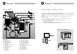
LEGEND
A
Max. power adjustment screw
B
Lock nut blocking adjustment
C
Spring
D
Min. power adjustment screw
E
Coil
F
Snap spring
G
Pressure tap
A
B
C
G
F
E
D
1009DIS866
1
Regulation for slow starting
2
System power regulation
3
B/P NATURAL GAS bridge
4
Bridge limiting starting
5
Bridge for floor heating
By cutting bridge 5, the boiler will self-regulate
to a max. heating temperature of 40
°
C.
74
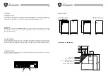
TIPO DE GAS
(
A
) Terminal de compensación
(
B
) Tubito de conexión
Para regular la válvula de gas proceda de la
siguiente manera:
a)
quite el tubito (
B
) del terminal (
A
)
b)
efectué la regulación
c)
vuelva a conectar el tubito (
B
) al terminal (
A
)
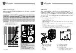
REGULACIÓN INYECTORES
Los grupos térmicos ya salen del establecimiento industrial regulados y listos para funcionar con GAS
NATURAL y GAS LÍQUIDO. Estas regulaciones están efectuadas sin la conexión del terminal de compensación
(Posic.A versión MBS W).
Para efectuar las regulaciones véase la siguiente tabla:
9.3 11.6 13.9 16.2 18.6 20.9 27.9 34.8
1009DIS1062
6,1
7,7
5,1
2,9
2,3
34
32
30
28
26
24
22
20
18
16
14
12
10
8
6
4
2
0
3.4
3.2
3.0
2.8
2.6
2.4
2.2
2.0
1.8
1.6
1.4
1.2
1.0
0.8
0.6
0.4
0.2
0
25,7
MB
25,5
MBS
33,1
MBS
32,7
MB
11,3
MB
12
MBS
G.N.
B
P
kPa
mbar
kW
* Presión mínima
WILO
1009DIS1081
A
B
min.
max.
min.
max.
m
3
/h
ømm
ømm
H
H
PRESIÓN EN LOS INYECTORES mbar
CAUDAL
Inyectores quemador
Diafragma gas
GAS NATURAL
2,9
11,3
2,3
12
3,01
1,2
1,2
-
-
B-G30 28/30 mbar
6,1
25,7
5,1
25,5
0,87
0,75
0,77
5,4
5,8
P-G31-37 mbar
7,7
32,7
6,1
33,1
1,15
0,75
0,77
5,4
5,8
P.C.I.
GAS NATURAL G20 8550 Kcal/h
GAS LÍQUIDO B-G30 29.330 Kcal/h
GAS LÍQUIDO P-G31 22.360 Kcal/h
LED 24MB W TOP LED 24MBS W TOP
LED 24MB LED 24MBS LED 24MB LED 24MBS


