Lamborghini Caloreclima GASTER N 56 AW Скачать руководство пользователя страница 29

29

EN

cod. 3540S420  -  05/2010  (Rev. 00)

EN

1. GENERAL INSTRUCTIONS

Carefully read the instructions contained in this instruction booklet.

After boiler installation, inform the user regarding its operation and give him this manual, which is an integral
and essential part of the product and must be kept with care for future reference.

Installation and maintenance must be carried out by professionally qualified personnel, according to current
regulations and the manufacturer's instructions. Do not carry out any operation on the sealed control parts.

Incorrect installation or inadequate maintenance can result in damage or injury. The Manufacturer declines
any liability for damage due to errors in installation and use or failure to follow the instructions.

Before carrying out any cleaning or maintenance operation, disconnect the unit from the power supply using
the system switch and/or the special cut-off devices.

In case of a fault and/or poor operation, deactivate the unit and do not attempt to repair it or directly intervene.
Contact professionally qualified personnel. Repair/replacement of the products must only be carried out by
professionally qualified using original spare parts. Failure to comply with the above could affect the safety of
the unit.

This unit must only be used for its intended purpose. Any other use is considered improper and therefore
dangerous.

The packing materials are potentially hazardous and must not be left within the reach of children.

The images given in this manual are a simplified representation of the product. In this representation there
may be slight and insignificant differences with respect to the product supplied.

2. OPERATING INSTRUCTIONS

2.1 Introduction

Dear Customer,

Thank you for choosing 

PEGASUS 56

, a floor-standing boiler 

FERROLI

 featuring advanced de-

sign, cutting-edge technology, high reliability and quality construction. Please read this manual
carefully and keep it for future reference.

PEGASUS 56

 is a high-efficiency heat generator for central heating using natural gas or liquefied

gas (configurable at the time of installation) and regulated by an advanced electronic control sys-
tem.

The boiler shell consists of cast-iron elements whose particular shape guarantees high exchange
efficiency under all operating conditions and an open-flue burner equipped with electronic ignition
and ionization flame control.

The boiler is also equipped with a 

temperature limiter

 (safety thermostat) and 

a fume evacuation

control device

 (fume thermostat).

Thanks to the electronic flame control and ignition system, boiler operation is mostly automatic.

The user only has to set the temperature required inside the home (by means of the optional room
thermostat, whose installation is recommended) or adjust the temperature of the system.
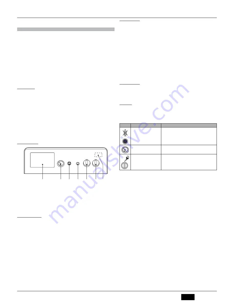
2.2 Control panel

fig. 1 - Control panel

Key

1

Arrangement for Thermostatic Controller

2

Boiler pressure/temperature gauge

3

Fume thermostat cover

4

Flame controller reset button with shutdown light

5

Boiler control thermostat

6

0-1-Test switch

7

Automatic reset safety thermostat (located inside the panel)

2.3 Turning on and off

Lighting

Open the gas cock ahead of the boiler

Turn on the switch or insert the plug (if present) ahead of the boiler

Turn the main switch 

“6”

 to position 

1

 (fig. 1).

Turn the knob 

“5”

 to the selected temperature and that of the room thermostat (if present) to

the required temperature value. The burner will light and the boiler begins to function auto-
matically, controlled by its adjustment and safety devices.

If the boiler is equipped with an electronic thermostatic controller fitted in position 

1

 of fig. 1,

the user must also take into account the manufacturer's instructions.

A

If the burners do not light and the pushbutton-shutdown indicator 

4

 comes on after cor-

rectly carrying out the lighting procedures, wait about 15 seconds and then press the
above pushbutton. The reset controller will repeat the lighting cycle. If the burners do not
light even after several attempts, contact an authorised service centre or qualified per-
sonnel.

Turning off

Close the gas cock ahead of the boiler, turn knob 

“6”

 to 0 and disconnect the power to the unit.

B

To avoid damage caused by freezing during long idle periods in winter, it is advisable to
drain all water from the boiler and system; or add a suitable antifreeze to the heating sys-
tem.

The boiler switch 

6

 has 3 positions “0-1-TEST”; the first two have the on-off function, the

third (unstable) must only be used for service and maintenance purposes.

2.4 Adjustments

System temperature adjustment

Turn the knob 

5

 of fig. 1 clockwise to increase the heating water temperature, or anti-

clockwise to decrease the temperature. The temperature can be varied from a minimum
of 30°C to a maximum of 90°C. However, it is advisable not to operate the boiler below
45°C.

Room temperature adjustment (with optional room thermostat)

Using the room thermostat, set the required room temperature. Controlled by the room
thermostat, the boiler lights and brings the system water to the temperature set by boiler
control thermostat 

5

 of fig. 1. The generator turns off when the required temperature in

the rooms is reached.

If the room thermostat is not present, the boiler will keep the system at the temperature
set by the boiler control thermostat.

Water system pressure adjustment

The filling pressure with system cold, read on the boiler water gauge detail 

2

 of fig. 1,

must be approx. 1.0 bar. If, during operation, the system pressure falls (due to the evap-
oration of gases dissolved in the water) to values below the minimum described above,
the User must bring it to the initial value by operating the filling cock. At the end of the
operation always close the filling cock.

2.5 Maintenance

The user must have the heating system serviced by qualified personnel at least once a
year and combustion checked at least every two years. Consult sec. 4.3 of this manual
for more information.

The boiler casing, panel and aesthetic parts can be cleaned with a damp soft cloth, if nec-
essary soaked in soapy water. Do not use abrasive detergents and solvents.

2.6 Faults

Given below are the faults that can be caused by simple, user-solvable problems.

A

Before calling the after-sales service, check that the problem is not due to no
gas or power.

1

2

3

4

5

6 7

Symbol

Fault

Cure

Boiler shutdown by the flame con-
troller

Make sure the gas cocks ahead of the boiler and on the meter are 
open.
Press the lit pushbutton-indicator.
In case of repeated boiler shutdowns, contact the nearest after-
sales service centre.

Boiler shutdown due to insufficient 
system pressure (only if a water 
pressure switch is installed)

Fill the system to 1-1.5 bar cold by means of the system filling 
cock.
Close the cock after use.

Boiler shutdown due to insufficient 
evacuation of fumes

Unscrew the fume thermostat cover and press the button below.
In case of repeated boiler shutdowns, contact the nearest after-
sales service centre.

Содержание GASTER N 56 AW

Страница 1: ...ZIONE E LA MANUTENZIONE INSTRUCCIONES DE USO INSTALACI N Y MANTENIMIENTO KULLANMA KURULUM VE BAK M TALIMATLAR INSTRUCTIONS FOR USE INSTALLATION AND MAINTENANCE INSTRUCTIONS D UTILISATION D INSTALLATIO...

Страница 2: ...ura desiderato A questo punto il bruciatore si accende e la caldaia inizia a funzionare automaticamente controllata dai suoi dispositivi di regolazione e sicurezza Qualora la caldaia venga dotata di u...

Страница 3: ...dotte da acque aggressive E opportuno ricordare che anche piccole incrostazioni di qualche mil limetro di spessore provocano a causa della loro bassa conduttivit termica un notevole surriscaldamento d...

Страница 4: ...questo punto il bruciatore si accende e la caldaia inizia a funzionare automaticamente controllata dai suoi dispositivi di regolazione e sicurezza B Se dopo aver eseguito correttamente le manovre di a...

Страница 5: ...e della camera fumi fig 6 Pulizia della caldaia 1 Coperchio della mantellatura 2 Piastra di chiusura della camera fumi 3 Scovolo 4 Tappo per l analisi della combustione 5 Isolante Analisi della combus...

Страница 6: ...gelli gas sporchi o errati Controllare o pulire gli ugelli Ricambio d aria insufficiente Controllare che l aereazione del locale dove si trova l apparecchio sia suffi ciente per una buona combustione...

Страница 7: ...ramma perdite di carico A m3 H B m colonna d acqua Potenze Pmax Pmin Portata Termica Potere Calorifico Inferiore Hi kW 61 6 24 5 Potenza Termica Utile 80 C 60 C kW 56 0 21 6 Alimentazione gas Pmax Pmi...

Страница 8: ...iscaldamento 44 Valvola gas 49 Termostato di sicurezza 63 Termostato di regolazione caldaia 72 Termostato ambiente non fornito 82 Elettrodo di rivelazione 83 Centralina elettronica di comando 92 Termo...

Страница 9: ...mento 44 Valvola gas 49 Termostato di sicurezza 63 Termostato di regolazione caldaia 72 Termostato ambiente non fornito 82 Elettrodo di rivelazione 83 Centralina elettronica di comando 92 Termostato f...

Страница 10: ......

Страница 11: ...n y de seguridad En caso de que la caldera est equipada con una centralita electr nica termost tica monta da en la posici n 1 de fig 1 el usuario deber considerar tambi n las instrucciones propor cio...

Страница 12: ...ocos mil metros de espesor pueden causar graves inconvenientes Estas sustancias tienen una conductividad t rmica muy baja y por consiguiente las paredes de la caldera se calientan en exceso Si la inst...

Страница 13: ...ntrolada por los dispositivos de regulaci n y de seguridad B Si despu s de haber efectuado correctamente las operaciones de encendido los que madores no se encienden y el testigo del pulsador de rearm...

Страница 14: ...za de la caldera 1 Tapa del panelado 2 Placa de cierre de la c mara de humos 3 Cepillo 4 Tap n para el an lisis de la combusti n 5 Aislamiento An lisis de la combusti n En la parte superior del cortat...

Страница 15: ...l gas Inyectores del gas sucios o inadecuados Controlar o limpiar los inyectores Recambio de aire insuficiente Controlar que la ventilaci n del local donde se encuentra el aparato sea sufi ciente para...

Страница 16: ...de carga A m3 H B m columna de agua Potencias Pm x Pm n Capacidad t rmica poder calor fico inferior Hi kW 61 6 24 5 Potencia t rmica til 80 C 60 C kW 56 0 21 6 Alimentaci n de gas Pm x Pm n Inyector...

Страница 17: ...efacci n 44 V lvula de gas 49 Termostato de seguridad 63 Termostato de regulaci n de la caldera 72 Termostato de ambiente no suministrado 82 Electrodo de detecci n 83 Centralita electr nica de mando 9...

Страница 18: ...44 V lvula de gas 49 Termostato de seguridad 63 Termostato de regulaci n de la caldera 72 Termostato de ambiente no suministrado 82 Electrodo de detecci n 83 Centralita electr nica de mando 92 Termos...

Страница 19: ......

Страница 20: ...de yap lan ayarlamalar ve emniyet cihazlar ile kontrol edilmek zere oto matik olarak al maya ba layacakt r E er kombi de g sterilmekte olan 1 ek 1 pozisyonuna monte edilmi olan bir elektronik termosta...

Страница 21: ...k kire olu umunun bile kombi eperlerinin a r derecede s nmas na neden olaca n n ve sonu olarak ortaya ok ciddi sorunlar n karabilece inin unutulmamas gerekir ok b y k sistemlerde ok b y k miktarda su...

Страница 22: ...r l r yana cakt r ve kombi de yap lan ayarlamalar ve emniyet cihazlar ile kontrol edilmek zere otomatik olarak al maya ba layacakt r B Yakma i lemi prosed r n ba ar l bir ekilde ger ekle tirdikten son...

Страница 23: ...vermemeye dikkat ediniz ek 6 Kombinin temizli i 1 Muhafaza kapa 2 Duman odas kapatma plakas 3 F r a 4 Yanma analizi t pas 5 Yal t m maddesi Yanma analizi Dumanlar n rneklemesi amac yla bir nokta komb...

Страница 24: ...leme bas nc n kontrol ediniz Gaz u lar kirlidir veya ar zal d r U lar kontrol ediniz ve temizleyiniz Hava de i imi yetersiz Cihaz n monte edilmi oldu u ortamdaki havaland rman n verimli bir yanmay sa...

Страница 25: ...veriler tablosu 5 4 Diyagram Y k kayb ek 13 Y k kay plar diyagram A m3 s B m su s tunu G Pmaks Pmin Is tma G c D k Is tma De eri Hi kW 61 6 24 5 Faydal Is tma G c 80 C 60 C kW 56 0 21 6 Gaz beslemesi...

Страница 26: ...rotu 32 Is tma sirk lat r 44 Gaz valf 49 Emniyet termostat 63 S cak su ayarlama termostat 72 Oda termostat cihazla birlikte verilmez 82 Tespit elektrotu 83 Elektronik kumanda merkezi 92 Duman termosta...

Страница 27: ...sirk lat r 44 Gaz valf 49 Emniyet termostat 63 S cak su ayarlama termostat 72 Oda termostat cihazla birlikte verilmez 82 Tespit elektrotu 83 Elektronik kumanda santrali 92 Duman termostat 98 Sivi 129...

Страница 28: ......

Страница 29: ...to the required temperature value The burner will light and the boiler begins to function auto matically controlled by its adjustment and safety devices If the boiler is equipped with an electronic t...

Страница 30: ...even scaling of just a few mm thick causes significant overheating of the boiler walls with consequent serious problems Water treatment is indispensable in the case of very large systems containing la...

Страница 31: ...uired temperature value The burner will light and the boiler be gins to function automatically controlled by its adjustment and safety devices B If the burners do not light and the pushbutton indicato...

Страница 32: ...fume chamber fig 6 Boiler cleaning 1 Casing cover 2 Fume chamber closing plate 3 Flue brush 4 Combustion analysis plug 5 Insulation Combustion analysis A fume sampling point has been included in the u...

Страница 33: ...pressure Gas nozzles dirty or wrong Check the nozzles and clean if neces sary Poor ventilation Make sure the ventilation in the room where the unit is located is sufficient for proper combustion Smel...

Страница 34: ...m3 h B m water column Powers Pmax Pmin Heating capacity Net Heat Value Hi kW 61 6 24 5 Available Heat Output 80 C 60 C kW 56 0 21 6 Gas supply Pmax Pmin Pilot nozzle G20 G25 mm 1 x 0 40 Pilot nozzle...

Страница 35: ...ating circulating pump 44 Gas valve 49 Safety thermostat 63 Boiler control thermostat 72 Room thermostat not supplied 82 Detection electrode 83 Electronic controller 92 Fume thermostat 98 Switch 129 R...

Страница 36: ...ating circulating pump 44 Gas valve 49 Safety thermostat 63 Boiler control thermostat 72 Room thermostat not supplied 82 Detection electrode 83 Electronic controller 92 Fume thermostat 98 Switch 129 R...

Страница 37: ...fonctionnement ont t r tablies le module de contr le r p tera le cycle d allumage Si m me apr s plu sieurs tentatives les br leurs ne s allumaient pas s adresser un centre de service apr s vente agr...

Страница 38: ...cas la vidange int grale ou partielle de l eau du circuit tait n cessaire il est recommand d ef fectuer le remplissage avec de l eau trait e Remplissage de la chaudi re et du circuit d installation L...

Страница 39: ...ux inflammables dans les alentours imm diats de la chaudi re Allumage de la chaudi re Ouvrir le robinet du gaz en amont de la chaudi re Purger l air dans la tuyauterie en amont de la vanne gaz Fermer...

Страница 40: ...s br leurs voir paragraphe suivant Nettoyer de haut en bas l aide d un couvillon La m me op ration peut s effectuer de bas en haut Nettoyer l aide d un aspirateur les conduits d vacuation des produits...

Страница 41: ...leurs gaz sales ou erron s Contr ler ou nettoyer les gicleurs Rechange d air insuffisant Contr ler que le local o se trouve la chaudi re est suffisamment a r pour assurer une bonne combustion Odeur de...

Страница 42: ...amme Perte de charge fig 13 Diagramme pertes de charge A m h B m colonne d eau Puissances Pmax Pmin Puissance thermique Pouvoir calorifique inf rieure Hi kW 61 6 24 5 Puissance thermique utile 80 C 60...

Страница 43: ...cuit chauffage 44 Vanne gaz 49 Thermostat de s curit 63 Thermostat r glage chaudi re 72 Thermostat d ambiance non fourni 82 lectrode de d tection 83 Module lectronique de commande 92 Thermostat fum es...

Страница 44: ...chauffage 44 Vanne gaz 49 Thermostat de s curit 63 Thermostat r glage chaudi re 72 Thermostat d ambiance non fourni 82 lectrode de d tection 83 Module lectronique de commande 92 Thermostat fum es 98...

Страница 45: ...cod 3540S420 05 2010 Rev 00 RU 1 2 2 1 PEGASUS 56 FERROLI PEGASUS 56 2 2 1 1 2 3 4 5 6 0 1 7 2 3 6 1 1 5 1 1 A 4 15 6 0 B 6 3 0 1 TEST 2 4 5 1 30 90 45 5 de 1 2 1 1 0 2 5 sez 4 3 2 6 A 1 2 3 4 5 6 7...

Страница 46: ...46 RU cod 3540S420 05 2010 Rev 00 3 3 1 B 3 2 3 3 20 C B 2 B 2 a1 1 a2 1 a3 1 2 25 Fr 1 1 5 2 3 4 B 2 B 3 5 230 50 B 3 3 A 3 cap 5 3 1 2 3 1 3 2...

Страница 47: ...2 4 5 1 5 4 6 cap 5 2 3 G20 G25 G30 G31 1 cap 5 2 3 4 G20 G25 D 4 G30 G31 E 4 3 4 4 A B C D G20 G25 E G30 G31 F 1 2 3 4 5 6 7 8 RESET 4 2 B 6 1 1 5 1 50 C B 15 3 4 6 3 0 1 TEST A cap 5 6 1 0 6 1 0 B...

Страница 48: ...48 RU cod 3540S420 05 2010 Rev 00 2 3 1 B 5 5 B 6 5 5 6 1 2 3 4 5 7 1 2 3 4 5 6 10 15 7 7 A 1 2 8 3 4 5 9 6 3 2 1 4 5 fig 8 fig 9...

Страница 49: ...49 RU cod 3540S420 05 2010 Rev 00 1 2 3 4 5 6 7 8 4 4 1 fig 10 3 3 4 mm 5 4 8 10 40 C...

Страница 50: ...13 A 3 B P P Hi 61 6 24 5 80 C 60 C 56 0 21 6 P P G20 G25 1 x 0 40 G31 1 x 0 24 G20 5 x 2 80 G20 20 G20 15 0 2 5 G20 3 6 52 2 59 G31 5 x 1 75 G31 37 G31 35 0 6 G31 4 82 1 92 C 95 6 6 0 3 5 16 6 850 6...

Страница 51: ...51 RU cod 3540S420 05 2010 Rev 00 5 5 14 24 32 44 49 63 72 82 83 92 98 129 159 160 A...

Страница 52: ...52 RU cod 3540S420 05 2010 Rev 00 15 24 32 44 49 63 72 82 83 92 98 129 159 160 A...

Страница 53: ...1 1 i 2 3 i i 4 i 5 6 0 1 7 i i i i 2 3 i i i 6 1 1 i 5 i i i i i i 1 1 i i i A i i 4 i 15 i i i i i i i i i i i 6 0 i i B i i i i 6 3 i 0 1 TEST i i i i i i i i i 2 4 5 1 i i i i i i i 30 90 i i 45...

Страница 54: ...i 1 a2 i i 1 a3 i 1 2 i i 25 Fr i i i i i i i i i i i i i i i i i i 1 i i i i i i i i i i i i i 1 5 2 3 4 B i i i i i i i i i i i i i i i i 2 i i i i i i i i i i i i i i i i i i i i i i i i i i i i i...

Страница 55: ...4 5 6 7 I I i 8 RESET 4 2 B i i i i i i i i i i i i i i i i i i i i i i i i i i i i i i i i i 6 1 1 i 5 1 i i i 50 C i i i i B i i i 15 i i i i 3 4 i 6 3 i 0 1 TEST i i i i i i i i i i A cap 5 6 1 0 i...

Страница 56: ...B i i 6 i i i 5 i i i 5 i i i i i i i i i i i i i i i i i i i i i 6 1 2 i i 3 4 i 5 I i i i i i i i 7 1 i i 2 i i i i 3 i i i i 4 5 6 10 15 7 7 A i i i i i i i 1 i i i 2 i 8 3 i i 4 i i i i i 5 i i i...

Страница 57: ...4 1 i fig 10 i 3 3 4 mm 5 4 8 i i i i i i i i i i i i i i i 10 i i i i i i i i i i i i i i i i i i i i i i i i i i i i i i i i i i i i i i i i i i i i i i i i i i i i i i i i i i i i i i i i i i i i...

Страница 58: ...4 i 13 i A 3 B i Pmax Pmin i Hi 61 6 24 5 i 80 C 60 C 56 0 21 6 Pmax Pmin i G20 G25 1 x 0 40 i G31 1 x 0 24 i G20 5 x 2 80 G20 20 G20 15 0 2 5 G20 3 6 52 2 59 i G31 5 x 1 75 G31 37 G31 35 0 6 G31 4 82...

Страница 59: ...59 UK cod 3540S420 05 2010 Rev 00 5 5 i 14 24 32 44 49 63 72 i 82 83 92 98 129 i 159 160 i A i i i...

Страница 60: ...60 UK cod 3540S420 05 2010 Rev 00 15 i 24 32 44 49 63 72 i 82 83 92 98 129 i 159 160 i A i i i i...

Страница 61: ...dalla 93 68 Direttiva Compatibilit Elettromagnetica 89 336 modificata dalla 93 68 IT Uygunluk beyani LAMBORGHINI CALOR S p A Via Statale 342 CP46 44047 Dosso FE Italy bu cihazin asagida yer alan AET E...

Страница 62: ...CEE 90 396 92 42 73 23 93 68 89 336 93 68 RU D claration de conformit LAMBORGHINI CALOR S p A Via Statale 342 CP46 44047 Dosso FE Italy d clare que cet appareil est conforme aux directives CEE ci dess...

Страница 63: ......

Страница 64: ...532 359952 Export 0532 359947 Le illustrazioni ed i dati riportati sono indicativi e non impegnativi la LAMBORGHINI si riserva il diritto di apportare senza obbligo di preavviso tutte le modifiche che...

Отзывы: