41
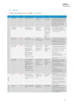
17. System Maintenance and Service
Diligent maintenance is the prime factor for assuring an error-free and efficient operation of the unit.
All the maintenance tasks contained in this chapter must be performed according to the maintenance
intervals.
17.1 Safety
All safety and warning instructions must be reviewed completely by all personnel prior to maintenance
work of the unit. Refer to
Improper Maintenance
WARNING
Danger of injury due to improperly performed maintenance.
Improper maintenance can lead to personal injury or material damage.
▪
Disconnect the unit from all sources of power during maintenance work.
▪
Ensure that there is enough working area at the beginning of the maintenance work.
▪
Provide all components and tools required for maintenance work.
▪
Keep the working area clean and tidy. Loose components and tools, which are lying on
each other or lying around, are sources of accidents.
▪
Check all components for soiling and damage. Do not use damaged or incorrect
components.
▪
Handle the components with care, to avoid damage.
▪
Assemble components properly. Comply with specified screw tightening torques.
▪
Secure components, to prevent them from falling or tipping over.
▪
Only perform maintenance work using conventional tools. Improper or damaged tools can
result in personal injury.
Handling Coolant
CAUTION
Danger of slipping or endangering the environment due to spilled coolant.
Spilled coolant can cause slipping and endanger those working in the environment.
▪
Do not spill coolant.
▪
Immediately remove the spilled coolant with an appropriate bonding agent.
▪
Dispose the bonding agent and coolant mixture in accordance with regional regulations.
NOTE
Testing and replacing external coolant hoses.
Coolant hoses can become brittle through age and must be checked at regular intervals.
▪
Observe the specifications of the coolant hoses manufacturer.
Содержание Nextreme NRC400
Страница 1: ...Nextreme Thermoelectric Chiller NRC400 Specification and User Manual ...
Страница 13: ...13 6 Component Locations Figure 2 Isometric Views of Unit Figure 3 Front View Figure 4 Rear View ...
Страница 24: ...24 Plumbing Refrigeration Diagram Figure 10 Plumbing and Refrigeration Diagram ...
Страница 27: ...27 11 2 Pump Performance Figure 14 Pump Performance with Cooling Fluids Water 30 EG W NRC 400 T0 00 PC2 ...
Страница 28: ...28 12 Chiller Dimensions Figure 15 NRC400 Chiller Overall Dimensions ...


