INSTALL AND CONNECT GAS SUPPLY LINES
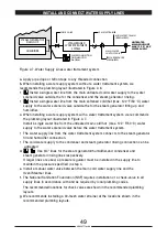
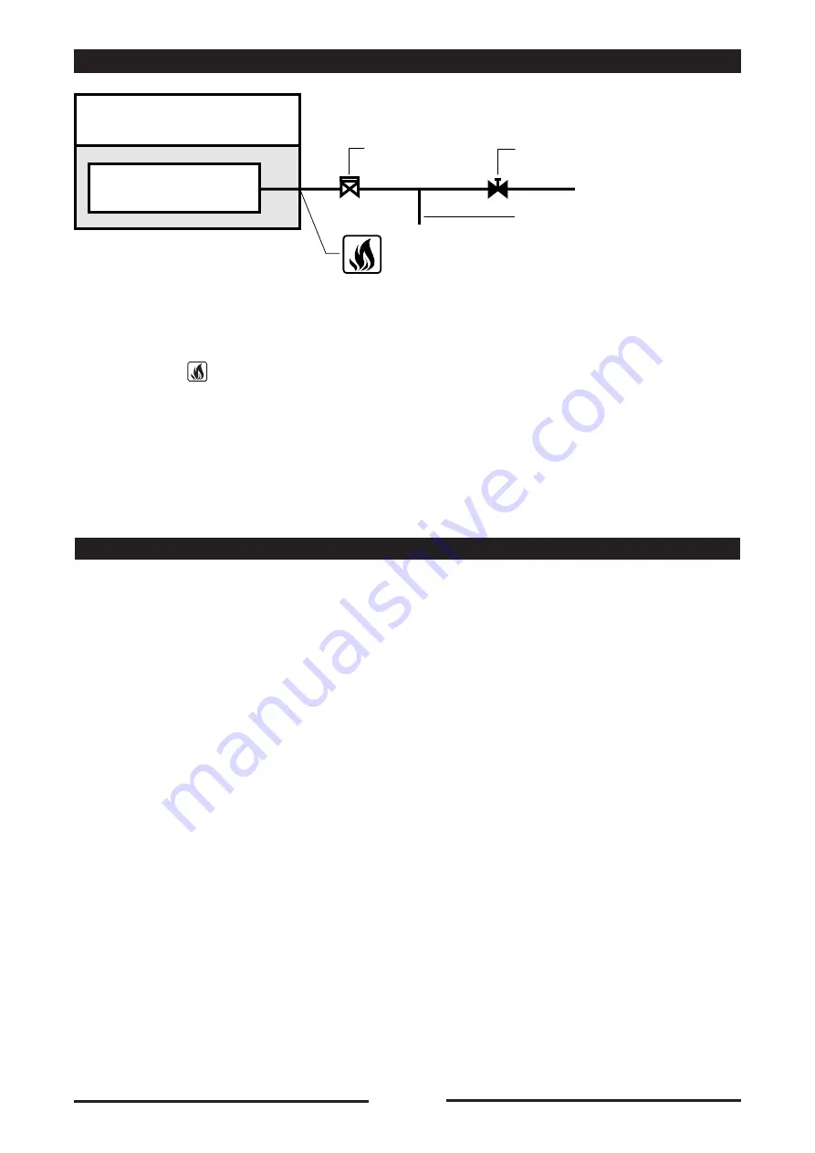
Figure 2-8. Recommended Gas Supply Line Layout
Install a manual shut-off valve between the gas supply line and the Oven/Steamer gas
connection (
on dimension drawing).
Install a sediment trap (drip leg) in the gas supply line, then connect gas supply piping to the
steam generator gas valve piping.
If natural gas pressure exceeds 14”/355,6 mm water column, a pressure regulating valve
must be installed in the gas supply plumbing to reduce the pressure to within the limits
specified in Gas Supply Requirements.
If Propane gas is supplied, use a gas pipe joint compound which is resistant to Propane gas.
TESTING GAS SUPPLY LINES AND BURNER CONTROLS
After initial installation, both the gas lines and burner controls should be inspected for proper
installation and tested for leaks and proper operation. After service or repair, the components
affected should be inspected and tested for leaks and proper operation.
Pressure Testing The Gas Supply Lines
The gas lines leading to the Oven/Steamer can be tested immediately after installation, or
during the Start-Up Checks. Do not supply gas to these lines until they have been tested.
When testing these lines observe the following.
Remove the right side access panel. Check all internal and external connections for proper tightness.
Refer to Figure 2-8, and set-up the Oven/Steamer automatic gas valve according to the test
pressure being used. The same pressure criteria apply when testing lines prior to the manual
gas shut-off valve.
• The appliance and its individual shut-off valve must be disconnected from the gas supply
piping system during any pressure testing of that system at test pressures in excess of
14”/355.6 mm water column (1/2 psi or 3.45 kPa).
• The appliance must be isolated from the gas supply piping system by closing its individual
manual shut-off valve during any pressure testing of the gas supply piping system at test
pressures equal to or less than 14”/355.6 mm water column (1/2 psi or 3.45 kPa).
51
90028771rev00
Oven/Steamer
AUTOMATIC GAS VALVE
IN
BURNER CONTROL SYSTEM
GAS SUPPLY CONNECTION
ON DIMENSION DIAGRAM
DRIP LEG
PRESSURE REGULATING
VALVE (IF REQUIRED)
MAIN GAS
SHUT-OFF VALVE
MAIN GAS SUPPLY
5
-
6
-
3
-
4
-
1
-
2
-
Содержание Naboo Compact CBEN061
Страница 2: ... 2 90028771rev00 ...
Страница 20: ... 20 90028771rev00 INSTALLATION DIAGRAMS ...
Страница 64: ... 64 90028771rev00 ...
Страница 65: ... 65 90028771rev00 65 90028771rev00 ...
Страница 66: ... 66 90028771rev00 66 90028771rev00 ...
Страница 67: ......

