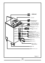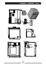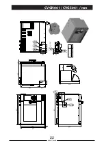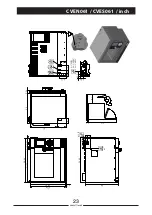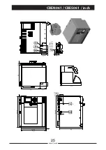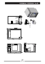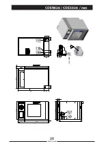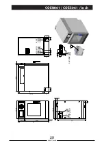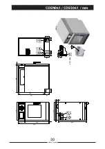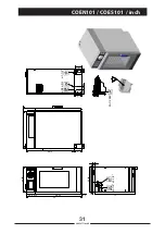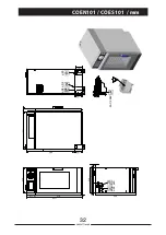
INSTALLATION DIAGRAM NOTES
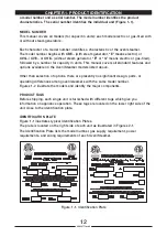
The Product Identification Plate located on the right side service panel specifies the
electric power requirements.
For each unit, the installer must provide a ground connection and a separate fused
disconnect switch.
Catastrophic damage will result from shifting the more than 3° out of level while power is
turned on at the unit’s main power switch.
The unit must have an untreated cold water
supply NOT HOT, and a HOT (max.
122 °F/50 °C) cold softened water
supply.
The softened water supply must meet the quality requirements of Table 2-2, and the
pressure requirements on installation diagrams (Fig. 2-2).
A Steamer Gard system is recommended when water quality does not meet the Table 2-2
requirements.
A manual water shut-off valve must be installed between the main softened water supply
and the steamer supply line. Refer to Figures 2-8 and 2-9 for recommended component
arrangements. A manual water shut-off valve must be installed between the main
untreated main water supply and the steam condenser supply line.
The drain line: use a heat-resistant plastic pipe (not flexible), installed without loops
or kinks and no longer than 2 meters with a slope of no less than 4 degrees, or realize
a drain line with a gravity flow away from the Oven. Drain line must not be connected
to the drain lines of any other equipment. In compliance with current standards, the
drainage piping must not be connected in a straight line.
It is advisable to interpose a funnel (see drawing) to facilitate flow.
DO NOT REDUCE
THE DRAIN LINE DIAMETER. DO NOT INSTALL A TRAP ON THE DRAIN LINE.
Never block the drain exhaust
vent
and at the top of the Oven.
WARNING
NEVER EXCEED 14”/355.6 mm WATER COLUMN (1/2 psi) GAS PRESSURE.
If the gas supply pressure exceeds 14”/355.6 mm water column, a pressure
regulating valve must be installed in the gas supply plumbing to reduce the gas
pressure to less than 14”/355.6 mm water column.
A main manual gas shut-off valve must be installed between the main gas supply and the
Oven/Steamer gas supply line.
Refer to figures 2-1 for the recommended component arrangements.
19
90028771rev00
1
-
2
-
3
-
4
-
5
-
6
-
8
-
9
-
7
-
10
-
10
-
11
-
11
-
12
-
Содержание Naboo Compact CBEN061
Страница 2: ... 2 90028771rev00 ...
Страница 20: ... 20 90028771rev00 INSTALLATION DIAGRAMS ...
Страница 64: ... 64 90028771rev00 ...
Страница 65: ... 65 90028771rev00 65 90028771rev00 ...
Страница 66: ... 66 90028771rev00 66 90028771rev00 ...
Страница 67: ......

