background image


19 

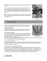
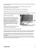
Compression” router bit.  With this bit, the up shear portion of the bit is less than ¼” in len

gth 

so that the bit can be used on ¼” veneered plywood and for dados.


5. 

 Form Router Bits 

Form Router Bits typically are available in standard profiles such as round over, ogee, etc.  
Router bits that have a shape associated with them would be classified with this group 


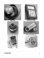
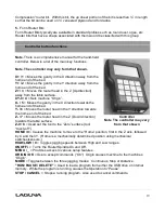
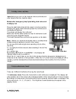
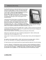
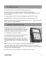
Controller button functions 


Note. 

There is a comprehensive manual for the hand-held 

controller. Below is a list of the main key functions.  

 
Note. The controller may vary form that shown.  
 
X+ / 1

 = Moves the gantry in the X direction away from the 

home end of the bed. 

Y+ / 2

 = Moves the gantry in the Y direction away from the 

home end of the bed.  

Z+ / 3

 = Moves the router head in the Z [Up direction] 

away from the table surface.  

XY-0 / 4

 = Sets 

machine “Origin”

X- / 5 

= Moves the gantry in the X direction towards the 

home end of the bed. 

Y- / 6 

= Moves the router head in the Y direction towards 

the home end of the bed. 

Z- / 7

 = Moves the router head in the Z (Down direction) 

towards the table surface. 

Z-0 / 8

 = 

Used set the tool to the “Zero” surface (tool 

“touch

-

off”

.) 

HOME / 9

Causes the machine to move to the “Home” position, 

first in the Z axis, followed 

by X and then Y.  (Home is a mechanically determined position using mechanical 
switches/sensors.) 

HIGH/LOW / 0

 = Toggles jogging speeds between High and Low ranges. 

ONOFF/. 

=  Turns the Router Spindle On and Off. 

MENU / _


= Provides access to various setup features. 

ORIGIN /OK 

Use to accept commands (“On”

.)  Origin causes machine to the machines 

“Origin”.


MODE

 = Toggles between the three jogging modes:  Continuous, Step or Distance. 

"RUN/ PAUSE / DELETE"

 = Used to load a program from either the USB drive or internal 

memory.  While the program is running, causes the 

Operation to “Pause”.


STOP / CANCEL

 =  Stops a running program.  Also used to cancel commands. 
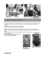


Controller      

Note The controller may vary 

from that shown 

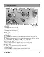
Содержание MCNC Swift 60 X 120-0233

Страница 1: ...lifornia 92606 Ph 800 234 1976 www lagunatools com MCNC Swift 48 X 96 0233 MCNC Swift 60 X 120 0233 MCNC Swift 48 X 48 1000 0233 2018 Laguna Tools Inc LAGUNA and the LAGUNA Logo are the registered tra...

Страница 2: ......

Страница 3: ...ssion 6 Specification sheet 6 Receiving your machine 7 Introduction to CNC machine 7 Parts of the CNC machine 8 What you will receive with the machine 10 Where to locate your machine 13 Unpacking your...

Страница 4: ...ed your supplying distributor Read carefully before operating the machine 1 Keep the working area clean and be sure adequate lighting is available 2 Do not wear loose clothing gloves bracelets necklac...

Страница 5: ...empted by others Laguna Tools Inc is not responsible for additional tools or modifications sold or performed other than from by Laguna Tools Inc on any Laguna Tools Inc machine Warranty maybe voided u...

Страница 6: ...tor 3 hp very quiet spindle 3 hp very quiet spindle 3 hp very quiet spindle Spindle 1 or 3 Phase Industrial Induction Spindle Liquid Cooled 1 or 3 Phase Industrial Induction Spindle Liquid Cooled 1 or...

Страница 7: ...shipping to customers as movement can take place during transportation It must be noted that additional machine movement can take place between Laguna Tools and the end user and some adjustments may...

Страница 8: ...e bed of the machine consists of a heavy steel frame and a T Slot Table The T slots are used to clamp the job or fixtures to the bed 2 Gantry The gantry straddles the bed and carries the router spindl...

Страница 9: ...a heavy welded construction that supports all the other parts of the machine 5 Electrical control box The electrical control box is located on the side of the machine in a dust free enclosure Caterpi...

Страница 10: ...10 7 Water pump The water pump provides coolant for the router spindle motor Running the router spindle without the cooling pump running can lead to spindle bearing failure Pump in water container...

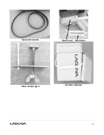
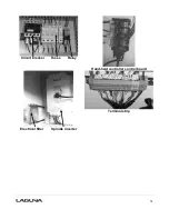
Страница 11: ...11 Spare drive belts Dust hood Wrenches Table clamps qty 8 Coolant container...

Страница 12: ...12 Water pump Hand held controller Collet nut with collet fitted Memory stick Max 8G Pipe fitting Plug Touch off puck...

Страница 13: ...let if fitted WARNING EXTREME CAUTION MUST BE USED BECAUSE THE BANDING WILL SPRING AND COULD CAUSE INJURY 2 Remove the box from the CNC machine if fitted and any other packaging material The parts ord...

Страница 14: ...shes are even with the tip of the router bits that you will be using If it is too low the brushes may drag on the job being cut and could be cut by the router bit If it is too high and is not in conta...

Страница 15: ...al L3 is not used Note When wiring the machine to your electrical system keep your cable as short as possible and the cable should not be allowed to run along the floor as this will cause a trip hazar...

Страница 16: ...freezing temperatures antifreeze must be added to the cooling water Connect the electrical plug to the pump cable Note A qualified electrician must carry out the electrical installation Lower the wat...

Страница 17: ...chine 1 Select a router bit and its relevant collet 2 Fit the collet into the spindle nut Press the collet into the spindle nut until it snaps into place Note The router bit must not be fitted into th...

Страница 18: ...standard twist drill is an example of this type of bit This bit design removes the chips from the kerf but has a tendency to chip the top surface especially veneers or melamine surfaces ball nose rout...

Страница 19: ...the X direction towards the home end of the bed Y 6 Moves the router head in the Y direction towards the home end of the bed Z 7 Moves the router head in the Z Down direction towards the table surface...

Страница 20: ...er lock key This isolates the machine and no functions can be operated when the key is in the off position It is recommended that when the machine is left unattended that the key if moved in the 0 pos...

Страница 21: ...hine Y Length from front to back when standing in front of the machine Z vertical up By pressing HIGH LOW 0 and MENU the display will change to AX 0 AY 0 and AZ 0 When the X Y and Z have an A in front...

Страница 22: ...and or Y axis 1 Press the mode button until Distance is displayed 2 Type in 100 and press OK 3 Pressing the X button will now move the router 100mm in the X axis The router head also move the set dis...

Страница 23: ...ates e g 1 9 1 Select Low Speed by pressing the HIGH LOW 0 button Select Continuous by press the mode button until Continuous is displayed The position of the router head as it changes will be shown a...

Страница 24: ...hed to the melamine surface with double stick tape Ideally the spoil board should positioned in the center of the machine s work envelope if possible to provide the greatest flexibility Using the desi...

Страница 25: ...is that it is scrap Moving the router head to the spoil board corner position 1 With the router head in the home position drop the router bit to just above the spoil board top face as described earli...

Страница 26: ...d as reference You need to apply three or four strips of double sided tape to the bed of the machine with sufficient length so that the spoil board is attached along its complete length 16 Clean the s...

Страница 27: ...s just touching the top of the spoil board When you fit the router bit into the collet the tip of the router bit will be at a different height above the spoil board and will have to be zeroed 1 Fit a...

Страница 28: ...ne will start to operate Note Ensure that you are clear of the machine as the spindle will start to turn and could cause injury 8 The router will just cut the surface of the spoil board the distance t...

Страница 29: ...e using the T slots You may find it convenient to clamp the job to the spoil board with the table clamps However note that this attachment method can only be used if the outside edges are not being ma...

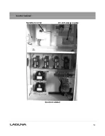
Страница 30: ...30 Control cabinet Spindle inverter 24 volt power supply Control cabinet...

Страница 31: ...31 Circuit breaker Fuses Relay Hand held controller control board Electrical filter Spindle inverter Terminal strip...

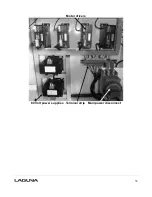
Страница 32: ...32 Motor drivers 80 Volt power supplies Terminal strip Main power disconnect...

Страница 33: ...r warn parts 4 The collets and spindle collet hole must be cleaned regularly Ensure that the slots in the collets are free of sawdust as sawdust builds up and will prevent the collet from compressing...

Страница 34: ...rectified 1 Internal breaker faulty Replace the breaker Motor tries to start but will not turn 1 With the power disconnected from the machine try to turn the spindle by hand If the spindle will not t...

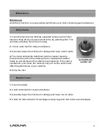
Страница 35: ...35 1 Machine not level on the floor Re level the machine ensuring that it has no movement...

Страница 36: ...ations subject to change Machines may be shown with optional accessories 2018 Laguna Tools Inc LAGUNA and the LAGUNA Logo are the registered trademarks of Laguna Tools Inc All rights reserved 2072 Alt...

Отзывы: