background image

OWNER'S MANUAL

(FOR MODELS MANUFACTURED SINCE 9/10)
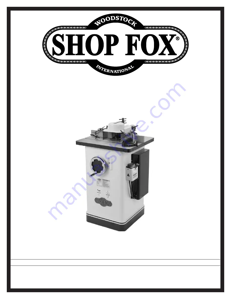
MODEL W1674

2 HP SHAPER

Phone: (360) 734-3482 • Online Technical Support: [email protected]

COPYRIGHT © FEBRUARY, 2004 BY WOODSTOCK INTERNATIONAL, INC., REVISED OCTOBER, 2010 (TR)

WARNING: NO PORTION OF THIS MANUAL MAY BE REPRODUCED IN ANY SHAPE OR FORM WITHOUT

THE WRITTEN APPROVAL OF WOODSTOCK INTERNATIONAL, INC.

Printed in Taiwan

#11875TS

Summary of Contents for Shop Fox W1674

Page 1: ...482 Online Technical Support tech support shopfox biz COPYRIGHT FEBRUARY 2004 BY WOODSTOCK INTERNATIONAL INC REVISED OCTOBER 2010 TR WARNING NO PORTION OF THIS MANUAL MAY BE REPRODUCED IN ANY SHAPE OR FORM WITHOUT THE WRITTEN APPROVAL OF WOODSTOCK INTERNATIONAL INC Printed in Taiwan 11875TS ...

Page 2: ...f personal protective equipment The manufacturer will not be held liable for injury or property damage from negligence improper training machine modifications or misuse Some dust created by power sanding sawing grinding drilling and other construction activities contains chemicals known to the State of California to cause cancer birth defects or other reproductive harm Some examples of these chemi...

Page 3: ...ch 20 Operation Overview 21 Stock Inspection Requirements 21 Cutter Rotation Direction 22 Cutter Height 22 Hold Downs 23 Fence Adjustment 24 Changing Speeds 25 Table Inserts 26 Installing Spindle 26 Cutter Installation 28 Safety Guard 31 Edge Cutting 33 Cutting Rabbets 35 Shaping Small Stock 36 Rub Collars 37 Irregular Shaping 38 Pattern Shaping 39 ACCESSORIES 40 Shaper Accessories 40 MAINTENANCE ...

Page 4: ...p operation maintenance and service of this product We stand behind our machines In the event that questions arise about your machine please contact Woodstock International Technical Support at 360 734 3482 or send e mail to tech support shopfox biz Our knowledgeable staff will help you troubleshoot problems and process warranty claims INTRODUCTION If you need the latest edition of this manual you...

Page 5: ... Adjustable Safety Guard Motor Cover Spindle Height Scale For Your Own Safety Read Instruction Manual Before Operating Shaper a Wear eye protection b Be sure keyed washer is directly under spindle nut and spindle nut is tight c Feed workpiece against rotation of cutter d Do not use awkward hand positions e Keep fingers away from spinning cutter use fixtures or jigs when necessary f Use overhead gu...

Page 6: ...t 2 3 4 Max Cutter Height 23 8 Max Cutter Diameter 5 Spindle Sizes 1 2 and 3 4 1 2 Exposed Spindle Length 35 8 3 4 Exposed Spindle Length 43 8 Spindle Travel 3 Spindle Speeds 7 000 and 10 000 Table Specifications Table Counterbore Diameter 5 Table Counterbore Depth 7 16 Number of Table Inserts 2 Table Insert Size ID 31 2 5 Table Length 21 Table Width 24 Table Thickness 11 4 Floor to Table Height 3...

Page 7: ...4 Electrical Power Requirement 110V 220V Single Phase Switch Rotary Switch Switch Voltage 220V Cord Length 10 ft Cord Gauge 14 gauge Recommended Breaker Size 20 15A Plug NEMA 6 15 Other Number of Dust Ports 1 Dust Port Size 3 Mobile Base Built In Customer Assembly Time Approximately 1 Hour Warranty 2 Year Country of Origin Taiwan Features Reversing Spindle Switch Large Precision Ground Cast Iron T...

Page 8: ...ie back or cover long hair Wear non slip footwear to avoid accidental slips which could cause a loss of workpiece control HEARING PROTECTION Always wear hearing protection when operating or observing loud machinery Extended exposure to this noise without hearing protection can cause permanent hearing loss MENTAL ALERTNESS Be mentally alert when running machinery Never operate under the influence o...

Page 9: ...ntal contact with moving parts or flying debris Make sure they are properly installed undamaged and working correctly before using machine NEVER STAND ON MACHINE Serious injury or accidental contact with cutting tool may occur if machine is tipped Machine may be damaged STABLE MACHINE Unexpected movement during operations greatly increases the risk of injury and loss of control Verify machines are...

Page 10: ... without special fixtures or jigs Where practical shape longer stock and cut to size Cutter positioning Keep the cutters on the underside of the workpiece whenever possible to reduce operator exposure to the moving cutter Testing for clearance Unplug the shaper and always rotate the spindle by hand to test any new setup for proper cutter clearance before starting the shaper Safely starting and fee...

Page 11: ... or fuse panel in your building and the incoming power connections at the machine The power supply circuit used for this machine must be sized to safely handle the full load current drawn from the machine for an extended period of time Circuit Requirements for 220V Prewired This machine is prewired to operate on a 220V power supply circuit that has a verified ground and meets the following require...

Page 12: ...tching receptacle see Figure 2 that is properly installed and grounded in accordance with local codes and ordinances For 220V Connection Prewired A NEMA 5 20 plug has a grounding prong that must be attached to the equipment grounding wire inside the included power cord The plug must only be inserted into a matching receptacle see Figure 3 that is properly installed and grounded in accordance with ...

Page 13: ...find an item on this list check the mounting location on the machine or examine the packaging materials carefully Occasionally we pre install certain components for safer shipping Box 1 Inventory Not Shown Qty A Shaper Unit 1 B Spindle Switch w Padlock Keys inside cabinet 1 Box 2 Inventory Figure 4 Qty C Fence Assembly 1 D Fence Boards 2 E Hardware Bag Flat Hd Screws 1 4 20 x 3 4 Fence Boards 4 Fl...

Page 14: ... 1 2 x 1 x 1 4 1 1 2 x 1 x 3 8 1 1 2 x 1 x 1 2 1 1 2 x 1 x 3 4 1 3 4 x 11 4 x 1 4 1 3 4 x 11 4 x 3 8 1 3 4 x 11 4 x 1 2 1 3 4 x 11 4 x 3 4 1 M Spindle Washers Spindle Washers 1 2 2 Spindle Washers 3 4 2 N Starting Pins 3 O Drawbar Drawbar Nut 1 Each P Spindle Spindle Nut 3 4 1 Each Q Spindle Spindle Nut 1 2 1 Each R Safety Guard Shaft 1 S Safety Guard Shaft Holder 1 T Handwheel 1 U Handwheel Handl...

Page 15: ...etroleum based solvents Most have low flash points which make them extremely flammable A risk of explosion and burning exists if these products are used Serious personal injury may occur if this warning is ignored ALWAYS work in well ventilated areas far from possible ignition sources when using solvents to clean machinery Many solvents are toxic when inhaled or ingested Use care when disposing of...

Page 16: ...e accessed from inside the shaper cabinet Alternately your shaper can be mounted on the Model D2057A Shop Fox Adjustable Mobile Base as shown in Figure 8 This method offers mobility and stability Figure 8 Model W1674 Shaper mounted on the Model D2057A Mobile Base Motor Shipping Braces To protect the motor and cabinet during shipping two red motor braces were installed with six hex bolts as shown i...

Page 17: ...ards and the safety guard are all independently adjustable Note Refer to the Fence Adjustment subsection on Page 24 for detailed operating instructions To install the fence assembly do these steps 1 Remove the two hex bolts three cap screws lock washers and flat washers from the back of the table top see Figure 13 Note The two hex bolts and lock washers are used when installing the safety guard wi...

Page 18: ...7 Slide the fence board assemblies into the front slots of the fence mounts then tighten the screws to hold them in place as shown in Figure 16 Figure 16 Fence boards installed Fence Boards 4 Make sure the mounting surface of the fence assembly and the table top are thoroughly clean then position the assembly on the table as shown in Figure 15 5 Align the fence base with the edge of the table then...

Page 19: ...ing Bar Short Safety Guard Guard Support Recommended CFM at Dust Port 400 CFM Do not confuse this CFM recommendation with the rating of the dust collector To determine the CFM at the dust port you must take into account many variables including the CFM rating of the dust collector the length of hose between the dust collector and the machine the amount of branches or Y s and the amount of other op...

Page 20: ...tle or no vibration Immediately turn the shaper OFF if you suspect any problems and refer to Page 50 to trouble shoot fix any problems before starting the shaper again If the source of an unusual noise or vibration is not readily apparent contact our technical support for help at 360 734 3482 or contact us online at tech support shopfox biz 6 Move the spindle switch to the STOP position wait for t...

Page 21: ...de articles or seek training from an experienced shaper operator before performing any unfamiliar operations Above all your safety should come first READ and understand this entire instruc tion manual before using this machine Serious personal injury may occur if safety and operational information is not understood and followed DO NOT risk your safety by not reading Always disconnect the machine f...

Page 22: ...he height position of the spindle in inches The FWD REV switch can be disabled and locked with a padlock While the padlock is inserted through the hole on the switch as shown in Figure 22 the motor cannot be started which reduces the risk of accidental startup by children or unauthorized users Figure 20 Spindle switch Figure 21 Height handwheel scale and spindle lock knob Height Handwheel Spindle ...

Page 23: ...10 Stops the machine Operation Overview Follow these rules when choosing and cutting stock Workpiece Material Your shaper and cutters are designed to cut wood and wood products ONLY DO NOT attempt to cut man made materials such as glass metal plastics etc that may cause the cutter or workpiece to break apart which could cause serious personal injury or property damage Foreign Objects Nails staples...

Page 24: ... of the cutter rotation before beginning operation and ALWAYS feed the stock into the cutter AGAINST the cutter rotation Feeding stock WITH the rotation of the cutter could pull the workpiece from your hands and draw your hands into the spinning cutter resulting in serious personal injury Direction Of Feed C o unterclockw i s e Figure 23 Cutter rotating counterclockwise The cutter height is adjust...

Page 25: ...wo turns making sure that the flat of the T nuts face down 4 Slide the assembly into the slot then tighten the cap screws to secure the bracket in place 5 Slide two hold down brackets onto the hold down bar as shown in Figure 27 insert the hold downs between the bracket and the bar then use two 1 4 20 x 3 8 set screws to secure the hold downs and the brackets 6 Insert the hold down bar into the ho...

Page 26: ...see Figure 29 3 Rotate the adjustment knob to move the fence mount in or out then re tighten the lock lever to hold it in place Note Use the pointer and scale shown in Figure 29 for precise adjustments Adjusting Fence Board Side to Side 1 DISCONNECT SHAPER FROM POWER 2 Loosen the fence board mounting screws see Figure 30 slide the board into the correct position for your operation then re tighten ...

Page 27: ...tter speed is changed by adjusting the V belt position on the motor and spindle pulleys as illustrated in Figure 32 To reposition the V belt on the pulleys do these steps 1 DISCONNECT SHAPER FROM POWER 2 Loosen the two hex bolts holding the motor mount to the spindle slide as shown in Figure 33 Do not remove the bolts completely 3 Slide the motor to the right then position the V belt on the pulley...

Page 28: ...W1674 comes with 1 2 and 3 4 shaper spindles It is very important that any spindle you use is properly seated into the spindle cartridge so that safety is maintained Tools Needed Qty Spindle Wrench Set 1 To install a spindle do these steps 1 DISCONNECT SHAPER FROM POWER 2 Thread the drawbar into the bottom of the spindle until it is snug as shown in Figure 35 3 Insert the spindle drawbar assembly ...

Page 29: ... side of the nut facing up as shown in Figure 37 Figure 37 Threading the drawbar nut with the tapered side facing up Drawbar Nut Tapered Side Up Figure 38 Tightening the drawbar nut 5 Use the spindle wrench set to tighten the drawbar nut until it is snug as shown in Figure 38 DO NOT overtighten the nut which could make removing the spindle difficult ...

Page 30: ...eep wood chips from falling into the cabinet provide better workpiece support and increase operator protection from the cutter Cutter Installation If the cutter is designed to remove material from the top of the workpiece we recommend you mount the cutter upside down then reverse the spindle rotation and feed direction In this configuration the workpiece provides a safety barrier between the cutte...

Page 31: ...ert as shown in Figure 39 4 Protecting your hands from the sharp edges slide a spindle washer and then the cutter onto the spindle making sure the cutting edges are facing in the right direction for your selected rotation see Figure 40 Figure 39 Installing a spindle spacer Spacer Figure 41 Placing the remaining spindle washer and spacer s onto the spindle Spindle Washer Figure 40 Placing a cutter ...

Page 32: ...ns on options for mounting the safety guard To avoid the risk of severe injury or amputation ALWAYS properly install the safety guard onto the shaper before connecting the machine to power Figure 43 Tightening the spindle nuts Figure 42 Installing spindle nuts Spindle Nuts Router bits are designed to only cut counterclockwise as viewed from the top When you are using a router bit adapter and route...

Page 33: ...e T lock handle to position the guard independently of the fence assembly Tools Needed Qty Phillips Screwdriver 2 1 To install the safety guard on the fence assembly do these steps 1 DISCONNECT SHAPER FROM POWER 2 Thread and hand tighten the guard support into the threaded hole on top of the fence assembly see Figure 44 3 From underneath the safety guard insert two 1 4 20 x 5 8 flat head screws in...

Page 34: ...st the flat to secure the shaft in place as shown in Figure 45 5 Slide the guard holding bracket onto the shaft then tighten the knob to hold it in place as shown in Figure 46 6 From underneath the safety guard insert two 1 4 20 x 5 8 flat head screws into the holes in the center of the guard then secure the longer guard mounting bar to the bracket with two 1 4 20 hex nuts 7 Secure the mounting ba...

Page 35: ... assuming the feed direction will be from right to left 3 With the stock held firmly against the infeed fence board adjust the fence board in or out until the stock contacts the cutter for the correct depth of cut then lock the infeed fence in position 4 Move the stock away from the cutter connect the shaper to power then start the spindle rotating counterclockwise 5 With the stock firmly held aga...

Page 36: ...ece past the cutter to verify the cut as illustrated in Figure 48 Note To reduce the effects of tearout cut the end grain first when putting an edge around the perimeter of a workpiece as illustrated in Figure 49 Direction of Feed Outfeed Fence Infeed Fence Figure 48 Fence boards setup for partial edge cutting Direction of Feed 1 2 3 4 Figure 49 Sequence for cutting the full perimeter of a workpie...

Page 37: ...e it above the table a distance equal to the height of the rabbet cut see Figure 50 Note To ensure good results for heavy cuts make multiple light passes and raise the cutter a small amount for each pass 3 Adjust the fence boards even with one another so that the cutter is exposed to the workpiece by a distance equal to the depth of the rabbet cut see Figure 50 4 Turn the machine ON and safely fee...

Page 38: ... of the stock selected in Step 3 as illustrated in Figure 51 Note Make the outline as close as possible to the cutter and spindle without interfering with rotation 5 Create countersunk mounting holes in the zero clearance fence so that the screws and T nuts from the split fence can be used to secure it to the mounting brackets in the same manner 6 Secure the zero clearance fence to the brackets ch...

Page 39: ...ng the risk of injury to the operator We DO NOT recommend using the rub collar below the cutter Rub collar above the cutter When the rub collar is used above the cutter the cut cannot be seen as illustrated in Figure 53 This offers the advantage that the cut is not affected by slight variations in thickness and accidental lifting will not damage the workpiece Simply correct any variation in height...

Page 40: ...DISCONNECT SHAPER FROM POWER 2 Remove the fence and safety guard assemblies 3 Insert a starting pin in the best suited hole on the cast iron insert ring as shown in Figure 57 4 Re install the safety guard using the free standing method before you connect the machine to power refer to Free Standing Safety Guard on Page 32 for detailed instructions 5 Make sure the cutter is properly oriented and ins...

Page 41: ...mplates allows identical parts to be shaped with speed and accuracy Shaping a pattern begins by attaching a pre fabricated template to the workpiece The edge of the template rides against a rub collar on the spindle as the matching profile is cut on the workpiece as illustrated in Figure 59 Follow these rules when making a template Design the template so that the cutting occurs underneath the rub ...

Page 42: ...o 31 2 high x 1 or wider with the optional Model W1107 12 Tracks or the Model W1108 24 Tracks The W1500 SHOP FOX Right Angle Jig allows you to make cuts on board ends and various other cuts with complete accuracy and improved safety Constructed using top quality aluminum castings and plates which are machined to exacting tolerances It has the perfect weight use ratio to dampen vibration yet is sti...

Page 43: ...n so that wood dust will not accumulate After cleaning re lubricate the appropriate parts Cleaning For optimum performance from your machine follow this maintenance schedule and refer to any specific instructions given in this section Note This maintenance schedule is based on average daily usage Adjust the maintenance schedule to match your usage to keep your shaper running smoothly and to protec...

Page 44: ... steps 1 DISCONNECT SHAPER FROM POWER 2 Use the spindle height handwheel to lower the spindle all the way then access the elevation assembly through the rear of the cabinet see Figure 60 3 Use mineral spirits shop rags and a stiff brush to clean away grease and built up grime from the surfaces of both slides and the threads of the leadscrew then apply a thin coat of gear grease to these surfaces 4...

Page 45: ... two hex bolts holding the motor mount to the spindle slide as shown in Figure 61 Do not remove the bolts completely 3 If the V belt is cracked excessively worn or damaged slide the motor to the right then replace the V belt 4 To tension the V belt slide the motor to the left until the V belt is snug then tighten the bolts The amount of V belt deflection between the pulley should be approximately ...

Page 46: ...safe condition and poor cutting results Tools Needed Qty Phillips Screwdriver 2 1 Standard Screwdriver 2 1 Precision Straightedge 1 To make the insert and insert ring level with the table top do these steps 1 DISCONNECT SHAPER FROM POWER 2 Remove the table insert then remove the three Phillips screws that secure the insert ring to the table top Note Notice that there is a barrel screw underneath e...

Page 47: ...ts to make the boards completely parallel with each other along their entire length Figure 65 Checking fence board parallelism Pulley Alignment Pulley alignment is important to the performance of your shaper If the pulleys are just slightly out of alignment the shaper may suffer from power loss and decreased V belt life When the pulleys are parallel and aligned with each other they are said to be ...

Page 48: ...ge as a guide rotate the motor assembly until the motor pulley is parallel with the spindle pulley then re tighten the four motor mount hex bolts 5 Replace the motor cover before connecting the machine to power Aligning Pulleys Tools Needed Qty Precision Straightedge 1 Wrench or Socket 12mm 1 To align the pulleys do these steps 1 DISCONNECT SHAPER FROM POWER 2 Reach into the rear of the cabinet th...

Page 49: ...o raise the spindle to its highest position Notice the movement of the handwheel If it is difficult to turn or you feel resistance from the spindle slide the gibs may need to be loosened 3 Use the spindle lock to hold the spindle in place then attempt to wiggle the top of the spindle If there is movement the gibs may need to be tightened Adjusting the Gibs Tools Needed Qty Wrench 12mm 1 Hex Wrench...

Page 50: ...ersonal injury fire or machine damage If you notice that any wires or components are damaged while performing a wiring task replace those wires or components before completing the task 5 MOTOR WIRING The motor wiring shown in these diagrams is current at the time of printing but it may not match your machine Always use the wiring diagram inside the motor junction box 6 MODIFICATIONS Using aftermar...

Page 51: ...R STOP REV Spindle Switch 220V Single Phase Motor Pre Wired 110V Motor 5 6 Gnd Gnd Gnd 5 6 Hot Hot Ground 110V NEMA 5 20 Plug As Recommended 220V Single Phase NEMA 6 15 Plug As Recommended G Neutral Ground Hot Rewired to 110V Rewired to 110V Figure 70 Motor wiring Figure 71 Spindle switch wiring wiring diagram ...

Page 52: ...belt slipping 4 Motor wired incorrectly 5 Plug receptacle at fault 6 Pulley slipping on shaft 7 Motor bearings at fault 8 Machine undersized for task 9 Motor overheated 10 Spindle switch at fault 11 Motor at fault 1 Only cut wood ensure moisture is below 20 2 Adjust fence jig 3 Tension replace V belt Page 43 4 Wire motor correctly Page 49 5 Test for good contacts correct wiring 6 Replace loose pul...

Page 53: ... have high moisture con tent or surface wetness 2 Dull cutter 1 Check moisture content and allow to dry if moisture is more than 20 2 Replace or have cutter professionally sharpened Chipping 1 Knots or conflicting grain direction in wood 2 Nicked or chipped cutter 3 Feeding workpiece too fast 4 Taking too deep of a cut 5 Cutting against the grain of the wood 1 Inspect workpiece for knots and grain...

Page 54: ... 11 10 8 6 5 4 36V2 35V2 33 32V2 69 34 3 39 40 38 38 3 75 45 37 71 51 46 47 48 49 50 70 29 22 26 16 16A 16B 17A 20A 52 20 56 59 21A 57 14 55 44 53 25 21 58 24 14 13 15 29 22 30 18 16B 16A 19 17B 17 22 30 20B 19 1 17B 2V2 3 37 65 66 67 28 28 68 39 72 PARTS Main ...

Page 55: ...EL 16A XPCAP04 CAP SCREW 1 4 20 X 1 2 50 XLABEL 12 READ MANUAL LABEL 16B XPSS03 SET SCREW 1 4 20 X 3 8 51 D3376 SHOP FOX NAMEPLATE 17 X1674017 POINTER 52 X1674052 FENCE RAM 17A XPS07 PHLP SCREW 1 4 20 X 3 8 53 X1674053 PINION SHAFT 17B XPW06 FLAT WASHER 1 4 55 XPCAP03 CAP SCREW 5 16 18 X 1 18 XPCAP17 CAP SCREW 1 4 20 X 3 8 56 XPW07 FLAT WASHER 5 16 19 X1674019 MAIN FENCE BRACKET 57 XPSS02 SET SCRE...

Page 56: ...TS Motor Assembly 129 128 126 131 133 134 135 136 141 147 148 117 118 146 145 139 150 140 144 123 122 121 111 114 110 103 101 104 116 115 127 143 142 149 132 123A 120 108 105 107 109 106 113 112 137 145 1 145 2 145 4 145 5 145 3 116 151 148 119 ...

Page 57: ... 4 113 X1674113 SPINDLE LOCK SCREW 142 XPW07 FLAT WASHER 5 16 114 X1674114 GIB 143 XPLW01 LOCK WASHER 5 16 115 XPSS20 SET SCREW 5 16 18 X 1 1 2 144 XPK12M KEY 5 X 5 X 30 116 XPN02 HEX NUT 5 16 18 145 X1674145 MOTOR 2HP 110 220V 1PH 60HZ 117 X1674117 ELEVATION HOUSING 145 1 XPC400A S CAPACITOR 400MFD 125VAC 118 XPB25 HEX BOLT 3 8 16 X 1 3 4 145 2 X1674145 2 CAPACITOR COVER 119 XPLW03 LOCK WASHER 3 ...

Page 58: ...4 SPACER 3 4 x 1 1 4 x 1 4 204 X1674204 SPINDLE CARTRIDGE 226 W1165 SPACER 3 4 x 1 1 4 x 3 8 205 XPK14M KEY 5 X 5 X 18 227 W1166 SPACER 3 4 x 1 1 4 x 1 2 206 X1674206 HOUSING CAP 228 W1167 SPACER 3 4 x 1 1 4 x 3 4 207 XPFH08 FLAT HD SCR 10 24 X 1 2 231 X1674231 SPINDLE WASHER 1 2 208 XP6204 BALL BEARING 6204 232 X1674232 SPINDLE WASHER 3 4 209 X1674209 SPACER LONG 233 X1674233 SPINDLE WRENCH SET 2...

Page 59: ...T 1 4 20 402 X1674402 SHAFT MOUNT 414 X1674414 EXTENSION BAR 403 XPLW04 LOCK WASHER 3 8 415V2 X1674415V2 OVERHEAD SAFETY GUARD V2 09 10 404 XPB18 HEX BOLT 3 8 16 X 1 416V2 XPFH02 FLAT HD SCR 10 24 X 1 405 X1674405 EXTENSION BRACKET 418 XPW06 FLAT WASHER 1 4 406 1 X1674406 1 LOCK KNOB SHAFT ASSY 419 X1674419 KNOB BOLT 1 4 20 X 1 2 409 X1674409 SHAFT 420 X1674420 TOP SAFETY GUARD 410 X1674410 HANDLE...

Page 60: ...SCRIPTION 601 X1674601 HANDLE 608 XPSS32 SET SCREW 10 24 X 3 4 602 XPW07 FLAT WASHER 5 16 609 XPSS29 SET SCREW 10 24 X 1 4 603 X1674603 MITER GAUGE BODY 610 X1674610 STOP 603 1 X1674603 1 COMPLETE MITER GAUGE ASSY 611 X1674611 POINTER 604 X1674604 MITER BAR 612 X1674612 SCALE 605 X1674605 SPECIAL WASHER 613 X1674613 GUIDE STUD 606 XPFH19 FLAT HD SCR 1 4 20 X 3 8 614 X1674614 SPECIAL PIN 3MM 607 XP...

Page 61: ...W1674 Owner s Manual Mfg After 9 05 ...

Page 62: ...tape along edges please do not staple Fold along dotted lIne Fold along dotted lIne Woodstock international inc p o box 2309 bellingham Wa 98227 2309 place stamp Here ...

Page 63: ...oodstock International Inc s warranty then the original owner must bear the cost of storing and returning the product This is Woodstock International Inc s sole written warranty and any and all warranties that may be implied by law including any merchantability or fitness for any particular purpose are hereby limited to the duration of this written warranty We do not warrant that Shop Fox machiner...

Page 64: ...High Quality Machines and Tools Woodstock International Inc carries thousands of products designed to meet the needs of today s woodworkers and metalworkers Ask your dealer about these fine products ...

Reviews: