


HUMMEL
®
01.12.2012
English / Englisch
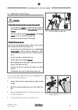
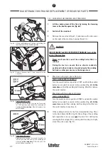
Fig. 73
To check the machine setting, tilt the machine
backwards.
Ensure that the machine is standing
securely!
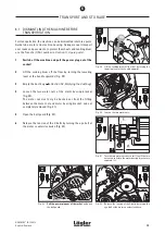
Fig. 74
Take the actual position of the adjustable wheel
using the setting fixture (right-hand wheel seen
from below).
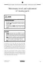
MAINTENANCE WORK AND REPLACEMENT OF WEARING PARTS
7
2
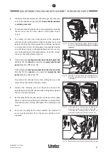
Tilt the machine backwards over the safety guards so that you
can see the wheel bearings (Fig. 73).
Ensure that the machine
is standing securely!
3
The wheel on the belt guard side can be adjusted by releasing
the tension screw. The other wheel is firmly fixed using a
screw.
4
For setting, first take the actual position of the adjustable
wheel using the setting fixture (right-hand wheel seen from
below). Position the fixture against the machine housing in
such a way that it rests not only against the machine housing
on both sides, but also at the adjustable wheel. If necessary,
turn the threaded pin of the setting device. To do this, release
the nut of the setting fixture (Fig. 74).
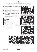
5
If the machine
is sanding more heavily on the belt guard side
(
A
in Fig. 75), the
wheel
must be adjusted
away from the belt
guard
(direction of
B
in Fig. 75).
If the machine
is sanding more heavily on the side cover side
(
C
in Fig. 75)
,
the
wheel
must be adjusted
towards the belt
guard
(direction of
D
in Fig. 75).
Now adjust the threaded pin of the setting device in the
relevant direction by the required amount.
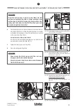
6
Release the clamping screw at the wheel clamp of the
adjustable wheel (Fig. 76) and place the setting fixture against
the machine housing again.
7
Set the wheel in the required position by means of the setting
fixture so that the wheel lining just still makes contact with the
threaded pin when turning, and tighten the clamping screw
again.
8
Carry out a sanding test to check whether the machine is
now correctly adjusted. If not, the process will have to be
repeated.
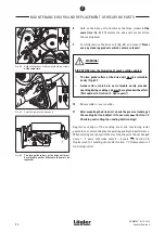
Fig. 75
If the machine is sanding more on side
A
, the
wheel must be adjusted in the direction of
B
.
If the machine is sanding more on side
C
, the
wheel must be adjusted in the direction of
D
.
Fig. 76
Release the screw on the right-hand wheel clamp.
37
Содержание HUMMEL
Страница 56: ...HUMMEL 01 12 2012 English Englisch SPARE PARTS 56 11...
Страница 58: ...HUMMEL 01 12 2012 English Englisch SPARE PARTS 58 11...
Страница 60: ...HUMMEL 01 12 2012 English Englisch SPARE PARTS 60 11...
Страница 64: ...HUMMEL 01 12 2012 English Englisch SPARE PARTS 64 11...
Страница 66: ...HUMMEL 01 12 2012 English Englisch SPARE PARTS 66 11...
Страница 68: ...HUMMEL 01 12 2012 English Englisch NOTES 68...
Страница 69: ...HUMMEL 01 12 2012 English Englisch NOTES 69...
Страница 70: ...HUMMEL 01 12 2012 English Englisch NOTES 70...