


42
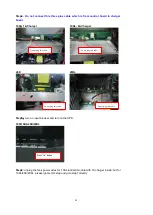
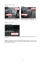
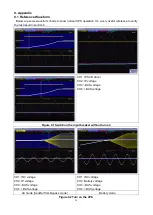
Step3:
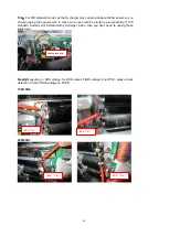
Measuring critical voltage signal as below
10K/10KL
20K/20KL
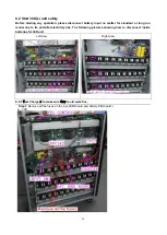
Section 3
:
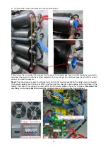
Turn on the UPS in battery mode to check if DC-DC BOOST and INVERTER
can work fine
1. Turn off input breaker.
2.
For 10k/10KL, Install the upper PSDR board; for 20k/20KL, please skip this step.
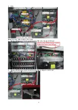
3.
Install control board, communication board and connect related wires,
please make sure
all signal cables are connected in right way.
4.
Please do not plug that three pins control wire first which connects control board
with charger board, otherwise the control board will shutdown charger and UPS
can not start up.
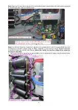
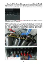
5.
For 10k standard model, due to the fact that 1A charger could provide very limited
power, around 240W,so please unplug the power wires of fans for PSDR board to
make sure ups could be started up successfully
.
For 10KL/20K/20KL, it is
unnecessary to unplug the fan power in this step.
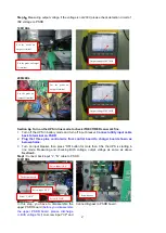
6.
Turn on input breaker, Press “ON” button for less than 0.5s, the LCD will be lit , confirm if
the battery voltage displaying on LCD is same as actual value(between 240-245V DC). If
everything above is ok, press the “ON” button for more than 0.5s and starting UPS.
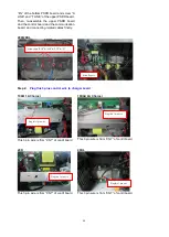
7. Please measure BUS voltage and output voltage as below picture, if everything is same
with the showing result, then UPS succeed in starting and is running in battery mode.
U3: +5V (the right leg)
U3: GND (the heat sink)
GND (the heat sink)
U5: -15V (the upper leg)
U4: +15V (the upper leg)
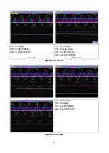
U13: GND (the heat sink)
U13: +5V (the right
leg)
GND (the heat sink)
U5: +15V (the right leg)
U9: -15V (the right leg)
Содержание G31 Series
Страница 37: ...37 ...


