


20
power SCR part.
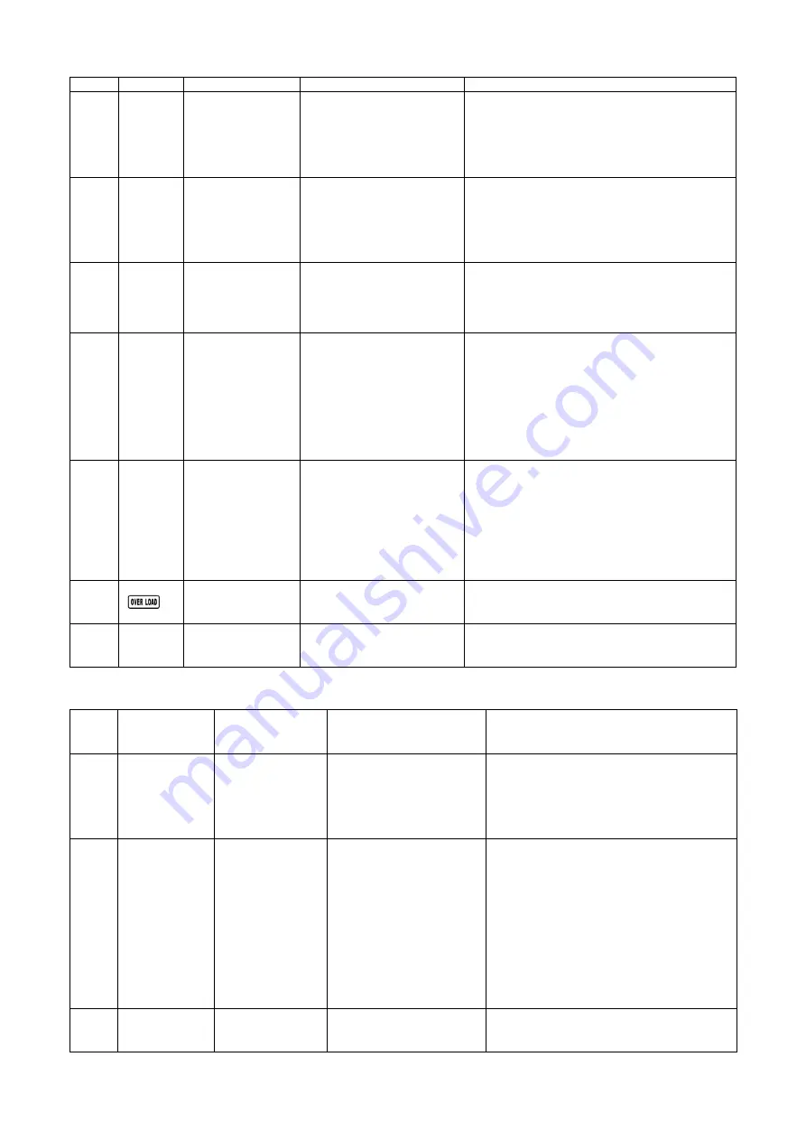
24
None
INV relay short
circuited
After
Bus
soft
start
completes and INV PWM is
off, more than 50V INV
voltage is detected, the
fault
signal
will
be
displayed.
Check if INV relay RY5(for 20KVA,check RY5
and RY6) on INV board is OK.
29
None
Battery
fuse
broken in Battery
mode
When this battery voltage is
less than 7V, any other
battery voltage is higher
than 9V
The fault signal will be
displayed.
Check the Battery fuse is ok
31
None
Parallel
cable
failure
When
the
parallel
communication
between
the UPSs is interrupted, the
fault
signal
will
be
displayed.
Check the parallel cables between the UPSs
are normal, and the cable between the parallel
board and the control board are normal.
36
None
Current un-sharing
When sharing current is
greater than 5A and sharing
current is greater than
5*ILoad
or
the
share
current less than 5A and
greater than the ILoad+4A
in UPS parallel system, the
fault
signal
will
be
displayed.
Check the share current cable are normal, and
make sure the output be connected together.
41
None
over temperature
The temperature of sink is
over the protection setting.
Check if UPS is overloaded, air vents are
blocked, and ambient temperature is over 40
℃
.
After overload or block is removed, please keep
UPS cool down for 10 minutes before turning on
again.
It is not recommended to operate the UPS
under over 40°C temperature environment.
43
Overload
The load is over the
settings for certain time.
Check the loads and remove some non-critical
loads.
Check whether some loads are failed.
46
None
Incorrect
UPS
setting
The UPS can not identify
the right model.
Check the Model Pin of the Control board is
inserted correctly
7.1.2.2 Fault code for 30k
Code
LCD icon
Fault Event
Description
Action
01
None
BUS
soft
start
failure
When the bus voltage
can’t reach the setting
value in 30s, the fault
signal will be displayed.
Check if power components such as IGBT
and SCR for the PFC and the utility power
SCR are well. Meanwhile, check if the
components on the drive circuit are well.
02
None
BUS voltage high
When one of the following
conditions occurs, the fault
signal will be displayed.
1. +Bus voltage keeps
higher than 450V or the
–BUS voltage keeps lower
than
–450V for more than
200ms.
Maybe the PFC board is damaged;
Check if power components such as IGBT
and SCR for the PFC and the utility power
SCR are well. Meanwhile, check if
components on the drive circuit are well.
03
None
BUS voltage low
When +Bus voltage keeps
lower than 300V or the
Maybe the PFC board is damaged.
Check if power components such as IGBT
Содержание G31 Series
Страница 37: ...37 ...


