


20
7
Then put the drawer module back in
place and line up the holes.
8
Use a hammer to start to insert the
screws into the floor.
9
Tighten the two screws into the floor to
secure the drawer module firmly.
10
Now refit the drawers. To do this, pull
the slides on both sides fully out,
including the inner ball-bearing slide.
11
Then fit the drawer slides inside the
drawer module slides.
12
When the slides are inserted, push the
drawer in fully. It may be a bit hard the
first time. Perform this operation to fit the
four drawers.
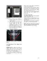
13
Finally, having fitted the top surface,
raise the screws on top at the back until
they meet the top surface. If the screws
fitted are not
long enough, change them
for the two longer ones supplied in a bag.
Wall
M6x30 or M6x50
Hexagonal screw
Top surface
Drawer module
Содержание Vulcano 7T E3 E/E
Страница 1: ...INSTRUCTIONS BOOK Vulcano 7T E3 E E Cookers...
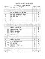
Страница 23: ...22 6 EXPLODED DIAGRAM VULCANO 7 E3 E E GENERAL EXPLODED DIAGRAM...
Страница 24: ...23 A VULCANO 7 E3 E E COOKER FRAME SUB COMPONENTS EXPLODED DIAGRAM...
Страница 25: ...24 B VULCANO 7 E3 E E FIREBOX DOOR SUBCOMPONENTS C VULCANO 7 E3 E E OVEN DOOR SUB COMPONENTS EXPLODED DIAGRAM...
Страница 28: ...27 H VULCANO 7 E3 E E UNDERNEATH OVEN DRAWER SUB COMPONENTS EXPLODED DIAGRAM...


