Lacunza Vulcano 7T E3 E/E Скачать руководство пользователя страница 16


15 

3.12. Drawer modules 
 

There  are  also  drawer  modules  which 
match  the  cooker  that  can  be  used  to 
organise  your  kitchen.  There  are  modules 
in 4 different dimensions: 
 
Drawer module 3 
Drawer module 4 
Drawer module 5 
Drawer module 6 


Drawer module 4 
 

3.13. Cooker maintenance. 
 

The cooker should be cleaned regularly along 
with the connecting duct and flue ways. 


3.13.1. Structure: 


The cooker should only be cleaned once it has 
become cold. 
The  structure  of  the  cooker  can  be  cleaned 
using a soft brush or damp cloth.  
The  enamelled  components  should  not  be 
cleaned  with  any  abrasive  product  or 
corrosive  product.  Cleaning  products  which 
contain chlorine or acids should not be used. 
A mild detergent such as washing up liquid is 
ideal. 
Always  wipe  any  condensation  or  spills 
immediately  as  these  can  leave  marks  on 
enamel  ort  can  rust  the  non-enamelled 
components. 
Pay special attention to any spills of acidic or 
alkaline  products  such  as  lemon  juice, 
ketchup, vinegar or ceramic cleaning products 
on  the  enamel  surfaces  as  these  products  can 
damage the enamel. 


3.13.2. Hob:  

Enamelled cast-iron top surface 
Enamelled area 


Clean these parts with a slightly damp 
cloth.  Do  not  use  abrasive,  corrosive, 
chlorine-based 

or 

acid-based 

products.  They  could  damage  the 
enamel.  If  water  condenses  or 
accidentally  splashes  on  the  cooker, 
clean  the  parts  affected  before  they 
dry;  otherwise,  the  colour  of  the 
enamel may be affected.


Polished cast iron 


Use special sandpaper and products to 
maintain. 


3.13.3. Firebox: 


Open  the  loading  door;  clean  all  the 
walls  of  the  firebox  (the  water 
jacket).  Soot  may  stick  hard  to these 
walls  and  make  it  very  difficult  to 
raise and lower the grille.


When  lighting  up  following  a  long 
period  without  use,  make  sure  that 
nothing is blocked. 


Keep  all  the  air  inlets  free  from 
blockage. 


3.13.4. Inside the cooker: 


To access the inside of cookers fitted 
with  cast-iron  top  surfaces,  lift  the 
polished  iron  section  and  the  cover 
on  the  right  of  the  surface.  You  can 
then  clean  the  oven  area  and  the  gas 
passage  between  the  oven  and  the 
right-hand side. 


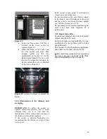
3.13.5. Gas flue socket:


The gas flue socket area must be kept 
clean  at  all  times  for  the  cooker  to 
work properly. 


It  must  be  cleaned  as  often  as 
required.  How  often  it  is  cleaned 
depends  on  how  much  the  cooker  is 
used and the type of fuel employed. 


Rear  gas  flue  socket.  The  flue  is 
accessed by opening the hatch at the 
back of the oven (Figure 18).  


Содержание Vulcano 7T E3 E/E

Страница 1: ...INSTRUCTIONS BOOK Vulcano 7T E3 E E Cookers...

Страница 2: ...de modules Page 14 3 11 Lifting grate mechanism Page 15 3 12 Drawer modules Page 15 3 13 Cooker maintenance Page 15 3 14 Maintenance of the chimney and sweeping Page 16 3 15 Important advice Page 16 3...

Страница 3: ...al Heat Output 0 17 Gas mass flow at Nominal Heat Output g s 22 Gas temperature downstream of flue socket at Nominal Heat Output C 255 Optimum flue draught Pa 12 Wood consumption beech at Nominal Heat...

Страница 4: ...and burden greater than those mandated by the regulations performance values emissions not limited radiation temperatures over the parameter set by the regulations Figure No 1 Dimensions in mm of Vulc...

Страница 5: ...l side insulation modules Removable cast iron flue socket Automatic thermostatically controlled combustion for primary and secondary air Easy Lighting System Large capacity ashpan The appliance must b...

Страница 6: ...l an outdoor air intake not sealed of a section of at least 90 cm2 Hearth Make sure that the floor is able to take the full weight of the cooker If the floor cannot it will need to be strengthened pri...

Страница 7: ...sembly of the gas flue The flue outlet diameter is 150mm internal diameter 2 5 Connection to the chimney The flue spigot which connects the appliance to the flue must be fitted in accordance to local...

Страница 8: ...such as a leak radiator a heat discharge valve a cold water supply etc The heating circuit must also have a purging valve at the bottom in order to drain it down The circuit must be fitted with a cir...

Страница 9: ...The following hydraulics diagrams illustrate the different types of central heating systems to which this appliance can be connected but are not to be used as working drawings Example 1 open plumbing...

Страница 10: ...pacity of 135 180 litres be used with 1 flow and return pipes not exceeding 7 8m each in length Both the cylinder and the pipework should be well lagged to minimise heat loss In examples 1 and 2 an al...

Страница 11: ...ess coal Non permitted fuels Petroleum coke and liquid fuel Green wood Green or damp wood reduces the performance of the appliance and leads to soot and tar build up on the inner walls of the gas flue...

Страница 12: ...let regulator F1 open F2 closed D Oven thermometer G Flue damper Warning During the first firing of the cooker you may experience fumes and haze caused by the curing process This is quite normal but w...

Страница 13: ...ral logs with a diameter of between 10 and 16 cm is better For longer combustion periods use thicker logs When the firebox is loaded close the loading door 3 5 Ash removal Open the loading door and mo...

Страница 14: ...und the flue outlet and maintenance purposes When cooking certain foods the steam which accumulates during the cooking process of the food can be expelled from the oven through the flue To expel the s...

Страница 15: ...re next to the range The insulation side modules and the range have height adjustable legs figure 16 Figure 16 3 11 Lifting grate mechanism On the Vulcano 7T E3 E E model the height of the firebox gra...

Страница 16: ...namelled area Clean these parts with a slightly damp cloth Do not use abrasive corrosive chlorine based or acid based products They could damage the enamel If water condenses or accidentally splashes...

Страница 17: ...regularly If the cooker is operated frequently we recommend that the chimney is swept at least twice a year If the cooker is used rarely it still must be swept once a year at the least In case of a c...

Страница 18: ...tc Cold flue Reheat the flue as quickly as possible using newspaper and kindling to instant heat Smoke entering room during burning The room is depressed In facilities equipped with VMC half open a wi...

Страница 19: ...Dimensions of Vulcano drawer Module 6 in mm 4 3 Description Drawer modules in 4 different measurements to match the appearance of the Vulcano cooker 4 4 Characteristics 4 drawer modules in different s...

Страница 20: ...ontally until released Perform this operation until all 4 drawers are removed 3 Fit the drawer module in position and raise it to the required level by turning the legs with a wrench 4 Fit the bracket...

Страница 21: ...inner ball bearing slide 11 Then fit the drawer slides inside the drawer module slides 12 When the slides are inserted push the drawer in fully It may be a bit hard the first time Perform this operati...

Страница 22: ...e materials Even though the wall is not combustible the cooker should be separated from the wall by approx 3 cm 3 Fit the insulation module adjusting the height and leaving a small gap between the coo...

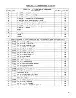
Страница 23: ...22 6 EXPLODED DIAGRAM VULCANO 7 E3 E E GENERAL EXPLODED DIAGRAM...

Страница 24: ...23 A VULCANO 7 E3 E E COOKER FRAME SUB COMPONENTS EXPLODED DIAGRAM...

Страница 25: ...24 B VULCANO 7 E3 E E FIREBOX DOOR SUBCOMPONENTS C VULCANO 7 E3 E E OVEN DOOR SUB COMPONENTS EXPLODED DIAGRAM...

Страница 26: ...25 D VULCANO 7 E3 E E FLUE SPIGOT SUB COMPONENTS EXPLODED DIAGRAM E VULCANO 7 E3 CAST IRON TOP FOR TOP FLUE CONNECTION SUB COMPONENTS EXPLODED DIAGRAM...

Страница 27: ...26 F VULCANO 7 E3 E E INSULATED COVER FOR TOP FLUE OUTLET SUB COMPONENTS EXPLODED DIAGRAM G VULCANO 7 E3 E E LEFT HAND SIDE DRAWER SUB COMPONENTS EXPLODED DIAGRAM...

Страница 28: ...27 H VULCANO 7 E3 E E UNDERNEATH OVEN DRAWER SUB COMPONENTS EXPLODED DIAGRAM...

Страница 29: ...no N 7 E3 Inferior flue baffle 1 Unid 4 VU 741 Vulcano N 7 E Superior flue baffle 1 Unid 5 VU 782 Vulcano N E3 LH double side panel 1 Unid 6 VU 615 Vulcano N 5 Stainless steel oven 1 Unid 7 VU 541 Vul...

Страница 30: ...e 1 Unid 43 IN 011 IN 700 Secondary air control knob 1 Unid C VULCANO 7 E3 E E OVEN DOOR SUB COMPONENTS EXPLODED DIAGRAM 44 VU 011 Vulcano N 5 7 External oven door 1 Unid 45 VU 021 Vulcano N 5 7 Inter...

Страница 31: ...491 Vulcano N 5 7 Handle fixing nut 2 Unid 78 VU 470 Vulcano N 5 7 handle fixing rod 1 Unid 79 VU 528 Vulcano N 7 Insolated cover inner panel 1 Unid 80 DIN7991 M5x20 SS allen screw 1 Unid 81 VU 469 V...

Страница 32: ...nner drawer panel 2 Unid 96 VU 272 Vulcano N 5 7 Revest Inferior Caj Horno Base inner drawer panel 1 Unid 91 VU 055 Vulcano N 4 5 7 8 Sop Cajon Izdo LHS handle bracket 1 Unid 92 VU 054 Vulcano 4 5 7 8...

Отзывы: