17
system, provides training in microwave safety
techniques.
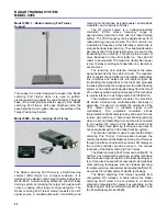
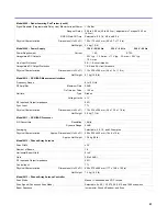
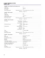
Model 9605 – Dual-Channel Sampler
The Dual-Channel Sampler performs time expansion of
the I- and Q-channel baseband signals from the radar
receiver in order to allow further processing and display.
It has three switches to select the system observation
range, as well as control knobs for adjusting the system
range origin, the balance of the I- and Q-channel output
signals, and the DC offsets at the I- and Q-channel
outputs. A time base output is provided to obtain an A-
scope display on a conventional oscilloscope.
Unregulated DC power is automatically supplied to
the Dual-Channel Sampler through self-aligning
connectors when it is installed on the Power Supply /
Antenna Motor Driver
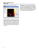
Model 9607 – Target Positioning System
The Target Positioning System positions a passive radar
target accurately. The system consists of a mobile target
table, a remote target controller module connected to the
table via a multiway cable, and four types of targets (a
sphere, a cylinder, a 90-degree reflector, three metal
plates and a plexiglass plate). The surface of the target
table measures 90 by 90 cm (35.1 x 35.1 in) and is
marked with a 1-cm (0.39-in) grid.
The system provides closed-loop DC servo control
of the position and speed of the target in X and Y. On
the target controller, either manual control of target
position and speed or one of four preprogrammed
trajectories can be selected. Two three-digit displays
give a readout of the X and Y position or speed of the
target. The target position can be controlled externally
using rear panel inputs.
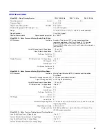
Model 9620 – Radar Transmitter
The Radar Transmitter is an instructional module
designed to provide training in system- and module-level
troubleshooting. It has switches that the instructor can
use to insert faults. These switches, as well as the circuit
boards and test points, are accessed through the hinged
door on top of the module.
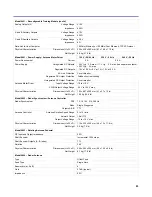
The Radar Transmitter generates an RF signal that
can be either frequency modulated or amplitude
modulated. It includes an RF oscillator, a pulse
generator, and an amplitude modulator.
The RF oscillator has a frequency modulator with
variable modulation frequency and deviation. It also has
a variable output frequency, which is indicated on
2½ digit display. An RF power switch allows the
RF output to be disabled.
The pulse generator produces the pulses required
by the system. It provides discrete and continuous
variation of the pulse width. The pulse generator output
signal controls the amplitude modulator to produce the
pulsed (amplitude-modulated) RF signal.
Unregulated DC power is automatically supplied to
the Radar Transmitter through self-aligning connectors
when it is installed on the Power Supply / Antenna Motor
Driver.


