background image

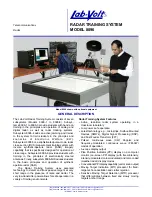
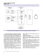
RADAR TRAINING SYSTEM
MODEL 8096

12

TABLE OF CONTENTS OF THE STUDENT MANUALS

Volume 1

Principles of Radar Systems (38542-00)

– Basic Principles of Pulsed Radar
– The Range-Delay Relationship
– Radar Antennas
– The Radar Equation
– Radar Transmitter and Receiver
– Antenna Driving System
– CW Radar and the Doppler Effect
– Frequency-Modulated CW Radar
– Troubleshooting a CW Radar
– Troubleshooting an FM-CW Radar
– Troubleshooting a Pulsed Radar: The RF Section

Volume 2

Analog MTI Processing (38543-00)

– Familiarization with the Analog Pulse Radar
– The PPI Display
– Phase-Processing MTI
– Vector-Processing MTI
– Staggered PRF
– MTI Limitations
– Threshold Detection
– Pulse Integration
– Sensitivity Time Control
– Instantaneous Automatic Gain Control
– The Log-FTC Receiver
– Constant-False Alarm Rate
– Troubleshooting the MTI Processor
– Troubleshooting the Display Processor
– Troubleshooting an MTI Radar System

Volume 3

Digital MTD Processing (38544-00)

– Familiarization with the Digital Pulse Radar
– The PPI Display
– Cell Mapping
– Fast Fourier Transform (FFT) Processing
– Constant False-Alarm Rate (CFAR)
– Correlation and Interpolation (C&I) Processing
– Surveillance (Track-While-Scan) Processing
– Troubleshooting the Digital MTD/PPI Processor

Volume 4

Tracking Radar (38545-00)

– Familiarization with the Tracking Radar
– Manual Tracking of a Target
– Automatic Range Tracking
– Angle Tracking Techniques
– Automatic Angle Tracking
– Range and Angle Tracking Performance (Radar-Dependent

Errors)

– Range and Angle Tracking Performance (Target-Caused

Errors)

– Troubleshooting a Radar Target Tracker

Volume 5

Radar in an Active Target Environment (38546-00)

– Familiarization with the Radar Jamming Pod
– Spot Noise Jamming and Burn-Through Range
– Frequency Agility and Barrage Noise Jamming
– Video Integration and Track-On-Jamming
– Antennas in EW: Sidelobe Jamming and Space

Discrimination

– Deception Jamming using the Radar Jamming Pod
– Range Gate Pull-Off
– Stealth Technology: The Quest for Reduced RCS
– Deceptive Jamming Using Amplitude-Modulated Signals
– Cross-Polarization Jamming
– Multiple-Source Jamming Techniques
– Chaff Clouds
– Chaff Clouds used as Decoys

Volume 6

The Phased Array Antenna (38547-00)

– Basic Principles, Operation and Adjustments
– The True-Time Delay Rotman Lens
– The Switching Matrix
– Beamwidth Measurement
– Radiation Pattern Measurement
– Angular Separation Measurement
– Phased Array Antenna Gain Measurement
– Maximum Scan Angle Measurement
– Target Bearing Estimation
– Target Speed Estimation

Содержание 8096

Страница 1: ...Finally subsystem 8096 8 introduces students to the basic principles and operation of synthetic aperture radar SAR The Radar Training System uses patented technology to detect and track passive target...

Страница 2: ...on jamming capabilities C Chaff cloud simulation C Radar cross section RCS measurement C Inverse synthetic aperture radar ISAR imagery capability C Phased array antenna C Operation as a Synthetic Aper...

Страница 3: ...llowing types of clutter and interference can be generated sea clutter rain clutter second trace echo noise and pulse interference The Radar Processor Display consists of a reconfigurable training mod...

Страница 4: ...the radar processing functions and adjust other parameters of the radar such as the video gain detection threshold etc see Figure 7 C control the radar display functions such as the PPI display mode...

Страница 5: ...e of radar which is implemented Figure 7 Computer based control of the radar processing functions and operating parameters Figure 8 Computer based control of the radar display functions Figure 9 Windo...

Страница 6: ...ls can be observed on the built in oscilloscope by connecting virtual probes to test points in the on screen block diagrams Figure 12 The Data Monitor is a powerful tool designed to study the various...

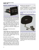
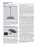
Страница 7: ...parabolic antenna a joystick type hand controller a set of accessories and a student manual Installation of the Radar Tracking Training System is very simple insert the interface module in the RTM mo...

Страница 8: ...diagrams connection of virtual probes in the on screen block diagrams observation of signals on the built in oscilloscope fault insertion etc The Radar Active Target RAT Training System Model 8096 4 i...

Страница 9: ...ed The system can also generate high resolution ISAR images of much larger targets when the shortest pulse width is used Because the system is based on pulse operation it does not need to be operated...

Страница 10: ...ively The trainer includes a phased array antenna a beam steering control module the necessary cables and a comprehensive student manual that deals with the principles of electronically steered antenn...

Страница 11: ...Positioning System Model 9607 1 included in the Basic Radar Training System and an antenna motion control module SAR controller Target radar echoes produced during a complete antenna scan are sampled...

Страница 12: ...lance Track While Scan Processing Troubleshooting the Digital MTD PPI Processor Volume 4 Tracking Radar 38545 00 Familiarization with the Tracking Radar Manual Tracking of a Target Automatic Range Tra...

Страница 13: ...SOR DISPLAY ADD ON MODEL 8096 2 QTY DESCRIPTION ORDERING NUMBER 4 1 Power Supply 9408 00 1 Reconfigurable Training Module 9431 10 1 Analog Digital Signal Combiner 9630 00 1 Data Acquisition Interface...

Страница 14: ...and Accessories 9690 D0 1 Monitor 9691 00 1 RCS ISAR Measurement Training System User Guide 39102 E07 RADAR PHASED ARRAY ANTENNA TRAINER ADD ON MODEL 8096 6 QTY DESCRIPTION ORDERING NUMBER 6 1 Phased...

Страница 15: ...n EW demonstrations Model 9601 Power Supply Antenna Motor Driver The Power Supply Antenna Motor Driver is the physical base for the Basic Radar Training System Several modules of the system are design...

Страница 16: ...nerates a command signal for output to the antenna motor driver The controller also generates azimuth information required by other system modules Unregulated DC power is automatically supplied to the...

Страница 17: ...the target in X and Y On the target controller either manual control of target position and speed or one of four preprogrammed trajectories can be selected Two three digit displays give a readout of t...

Страница 18: ...es contains all of the cables and accessories necessary for operation of the Basic Radar Training System Model 8096 1 These include SMA flexible cables BNC cables a DB9 cable an antenna motor driver c...

Страница 19: ...l these signals using a conventional oscilloscope DC power is automatically supplied to the Analog Digital Signal Combiner when it is installed into the RTM Model 9631 Data Acquisition Interface The D...

Страница 20: ...Computer is a Windows based computer with the LVRTS software installed two monitors and a dual output display adapter video card compatible with Microsoft DirectX version 9 or later The Radar Host Com...

Страница 21: ...from misconnections within the system Test points are available on the module s front panel to observe the signals on the BNC connector inputs and outputs using a conventional oscilloscope DC power i...

Страница 22: ...r The repeater which consists of an amplifier and a programmable delay line amplifies and delays the intercepted signal By transmitting this signal back to the radar and gradually increasing the delay...

Страница 23: ...S 8096 5 RCS AND ISAR MEASUREMENT TRAINING SYSTEM AND 8096 8 SAR TRAINING SYSTEM Model 9610 RCS ISAR Measurement Interface The RCS ISAR Measurement Interface contains additional RF circuitry that allo...

Страница 24: ...9611 SUBSYSTEM 8096 5 RCS AND ISAR MEASUREMENT TRAINING SYSTEM Model 9690 D Connection Leads and Accessories The Model 9690 D Connection Leads and Accessories contains a low RCS target support with a...

Страница 25: ...assive limiters two low loss long SMA cables a 30 dB SMA attenuator a DB25 cable and a microwave absorbing pen SUBSYSTEM 8096 8 SYNTHETIC APERTURE RADAR SAR TRAINING SYSTEM ADD ON TO 8096 5 Model 9614...

Страница 26: ...ntuitive user interface that provides all the controls and settings required to operate the Lab Volt synthetic aperture radar as well as to display fine SAR images Model 9690 F Connection Leads and Ac...

Страница 27: ...d Y Voltage Range 8 to 8 V PPI Output Z TTL Azimuth Input TTL On Screen Test Points 8 Faults 4 Model 8096 2 Radar Processor Display Digital Pulse Radar MTD Processor Functions Moving Target Detection...

Страница 28: ...ectable 1 2 and 5 ns Variable 0 6 to 5 5 ns Maximum Peak Power 200 mW Angular Accuracy 0 25E Model 8096 8 Synthetic Aperture Radar SAR Training System13 Operating Frequency 9 4 GHz Actual Aperture Bea...

Страница 29: ...regulated DC Output Protection Circuit breaker Antenna Motor Driver Input Voltage Range 10 to 10 V PWM Output Voltage Range 24 V to 24 V max Physical Characteristics Dimensions H x W x D 104 x 687 x 3...

Страница 30: ...Current 2 A 0 8 A Target Table Positioning Accuracy 0 5 cm 0 2 in Target Controller Speed Range 0 to 30 cm s 0 to 11 8 in s Programmed Trajectories 4 External Voltage Range 5 to 5 V External Input Im...

Страница 31: ...nge 8 to 10 GHz RF Amplifier Maximum Gain 22 dB On Time per Pulse 150 ns Limiters Type Diodes Voltage Limits 1 V RF Input and Output Impedance 50 Sync Input TTL Physical Characteristics Dimensions H x...

Страница 32: ...ut Power 0 5 dBm typical Impedance 50 Pulse Generator Pulse Width Ranges 1 2 5 1 to 5 ns Trigger Input TTL Output Level 300 mV Output Impedance 50 Faults 10 switch insertable Test Points 10 Physical C...

Страница 33: ...ut Interface Analog Outputs 4 Voltage Range 10 to 10 V Impedance 600 Digital Outputs 4 TTL Test Points 8 Physical Characteristics Dimensions H x W x D 114 x 110 x 209 mm 4 5 x 4 3 x 8 2 in Net Weight...

Страница 34: ...9614 02 9614 00 9620 10 9620 11 9620 12 9620 10 9620 11 9620 12 9620 10 9621 10 9621 11 9621 12 9621 10 9621 11 9621 12 9621 10 9630 00 9630 00 9630 00 9630 00 9630 00 9630 00 9630 00 9631 00 9631 00...

Страница 35: ..._____________________________________________________ _____________________________________________________________________________________________________ ____________________________________________...

Страница 36: ...ion facility has received the ISO 9001 certification Lab Volt reserves the right to make product improvements at any time and without notice and is not responsible for typographical errors Lab Volt re...

Отзывы: