RADAR TRAINING SYSTEM
MODEL 8096
4
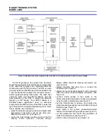
Figure 5. Simplified connection diagram of the Basic Radar Training System and Radar Processor/Display.
The RTM processes the signals from the Basic
Radar Training System to detect targets, and sends data
to the radar host computer via a high-speed data link
(Ethernet link with TCP/IP protocol). The RTM can also
generate clutter and interference which are added to the
I- and Q-channel echo signals from the radar receiver,
before signal processing takes place. The radar host
computer, which runs the LVRTS software, uses the
data produced by the RTM to display the detected
targets on a PPI display. The LVRTS software is a
Windows
®
-based application
2
used to download
programs into the DSP memory of the RTM, to select the
type of radar which is implemented (see Figure 6). It also
has an intuitive user interface to:
C
select the radar processing functions and adjust other
parameters of the radar, such as the video gain,
detection threshold, etc. (see Figure 7)
C
control the radar display functions such as the PPI
display mode selection, Variable Range
Marker (VRM), Electronic Bearing Line (EBL), etc.
(see Figure 8)
C
display diagrams that show how to connect the
equipment (see Figure 9)
C
display the functional block diagrams of the complete
radar and radar processor/display subsystem (see
Figure 10)
C
connect virtual probes to test points in the
aforementioned block diagrams to observe real signals
using the built-in oscilloscope (see Figure 11)
C
use the Data Monitor to observe and analyze the
signal processing sequence involved in Moving Target
Detection (see Figure 12)
C
insert faults in the system (password-protected
feature) for troubleshooting purposes (see Figure 13)
C
set the parameters that control the generation of
clutter and interference (see Figure 14)
C
obtain on-line help screens (see Figure 15)
2
LVRTS is compatible with the Windows
®
XP and Windows
®
7 operating systems.


