19
CAUTION
Check to make sure flue gases
DO NOT
recirculate into the air intake terminal when using direct venting. If the water
heater is having service issues, flue recirculation may be a contributing factor. Even when the minimum vent terminal
separation distances are followed, recirculation may still occur depending upon the location outside the building, the
distance from other buildings, proximity to corners, weather conditions, wind patterns, and snow depth. Periodically
check to make sure that flue recirculation is not occurring. Signs of flue gas recirculation include frosted or frozen intake
terminals, condensate in the intake terminal and venting system, oxidation or white chalk material on the flame sensor or
spark rod. Correction to flue recirculation may involve angling the intake away from the exhaust terminal, increasing the
distance between them, relocating the air intake to another side of the building, or using inside air for combustion. Check
to be sure the intake and exhaust terminals are not obstructed, especially during periods of below freezing weather.
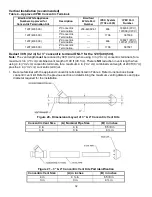
All intake and exhaust venting components
must
have the same diameter size.
DO NOT
use a different size on the
intake and exhaust venting. For 4 in
(10.2 cm)
venting, use the supplied 4 in
(10.2 cm)
vent terminals. For 3 in
(7.6 cm)
and 6 in
(15.2 cm)
venting, see the venting terminal section.
CAUTION
Be sure the condensate runs freely to a drain and does not accumulate inside the water heater. In cold climates,
precautions may need to be taken to ensure that the condensate drain does
NOT
freeze. Make sure a condensate trap
or drain loop is installed to prevent flue gases from being discharged into the room. Refer to the Venting section of this
Installation and Operation Manual for complete instructions on venting and condensate drainage.
High levels of dust and debris such as road and construction dust, insects, and tree pollen may clog the burner resulting
in poor performance and damage to the water heater. Avoid air intake locations where debris can be created such as
exhaust ventilation hoods, gravel parking lots, and near outdoor lights near vent terminals that attract bugs. For these
installations, an air intake filter kit, is available as an accessory service part from the installer of this water heater. The air
intake filter kit is
NOT
designed to filter out airborne contaminants or chemicals that may damage the water heater.
CAUTION
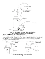
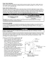
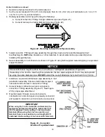
The vent shall terminate a minimum of 12 in
(30 cm)
above expected snowfall level to prevent blockage of vent
termination.
The horizontal centerline of the exhaust vent terminal (if applicable)
must NOT
be located lower than the horizontal
centerline of the air intake terminal if vented through the same wall.
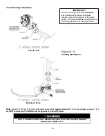
A service drain loop must be installed in the drain tubing to serve as a condensate trap to prevent flue gases from
escaping into the room.
DO NOT
position the air intake above the exhaust terminal.
NEVER
locate the air intake where exhaust gases can be introduced.
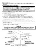
WARNING
To avoid damage or injury, there must be no materials stored against the water heater or vent-air intake system, and
proper care must be taken to avoid unnecessary contact (especially by children) with the water heater and vent-air
intake system.
UNDER NO CIRCUMSTANCES SHOULD FLAMMABLE MATERIALS, SUCH AS GASOLINE OR
PAINT THINNER BE USED OR STORED IN THE VICINITY OF THIS WATER HEATER, VENT-AIR INTAKE SYSTEM
OR IN ANY LOCATION FROM WHICH FUMES COULD REACH THE WATER HEATER OR VENT-AIR INTAKE
SYSTEM.
Содержание LUHE120T
Страница 42: ...42 BMS Wiring Diagram...
Страница 44: ...44 Lighting and Shutdown Instructions Figure 31 Lighting Instruction Label...
Страница 62: ......
Страница 63: ......


