20
Venting
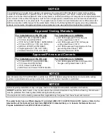
The venting instructions must be followed to avoid poor combustion or recirculation of flue gases. Such
conditions cause sooting or risks of fire and asphyxiation.
This water heater can be installed as either a power direct vent system or power vent system (air from
inside). If it is installed as a power direct vent system, then the air intake and the exhaust vent are piped to
the outside. If a power vent system is used, then combustion air is drawn from inside and only the exhaust
is piped to the outside. Determine which system is best for your application and install as described in the
following sections.
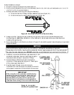
Vent Intake/Exhaust Terminals
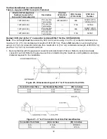
This water heater is supplied with a 4 in
(10.2 cm)
diameter screened intake elbow and exhaust coupling
referred to as the
‘air intake terminal’ and the ‘exhaust vent terminal.’ These 4 in
(10.2 cm)
supplied vent
terminals can be used with 4 in
(10.2 cm)
venting.
When venting with 6 in
(15.2 cm)
venting is desired, please discard 4 in
(10.2 cm)
vent terminals and use
field supplied 6 in
(15.2 cm)
fittings instead.
It is recommended to use a screen with square openings of 1/4
”x1/4” cut to a 7 ½ in
(19 cm)
diameter
circle. Then insert the screen into the field supplied intake/exhaust terminals.
When venting with 3 in
(7.6 cm)
venting is desired, please discard 4 in
(10.2 cm)
vent terminals and use
field supplied 3 in
(7.6 cm)
fittings instead.
It is recomm
ended to use a galvanized screen with square openings of 1/4”x1/4” cut to a 4 ½ in
(11.5 cm)
diameter circle. Then insert the screen into the field supplied intake/exhaust terminals.
Power Direct Vent Installation
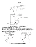
Venting may be run horizontally through an outside wall or vertically through a roof through using either 4 in
(10.2 cm),
3 in
(7.6 cm),
or 6 in
(15.2 cm)
diameter pipe. This water heater is supplied with a screened
intake elbow and exhaust coupling referred to as the
‘air intake terminal’ and the ‘exhaust vent terminal.’
Power Direct Vent Terminal Location
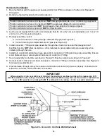
Plan the vent system layout so that proper clearances are maintained from plumbing and wiring. Before the
vent is installed, determine the vent pipe termination location as shown in Figure 11.
NOTICE
The air intake and exhaust terminals may be located on separate outside walls or one terminal may exit the
roof while the other is through the wall. The total combined equivalent vent length must be within the limits
specified in the venting tables and the intake length
CANNOT
exceed the exhaust by more than
30 ft
(9.2 m)
. The minimum recommended vent separation distance between the intake and exhaust
terminals is 36 in
(91.5 cm)
. Local conditions may require a need for greater vent separation distances.
Содержание LUHE120T
Страница 42: ...42 BMS Wiring Diagram...
Страница 44: ...44 Lighting and Shutdown Instructions Figure 31 Lighting Instruction Label...
Страница 62: ......
Страница 63: ......


