background image

46 


13. VOLTS   

 
1. Operate the Power button and turn on the instrument. Turn the rotary switch and select the 

VOLTS function. 

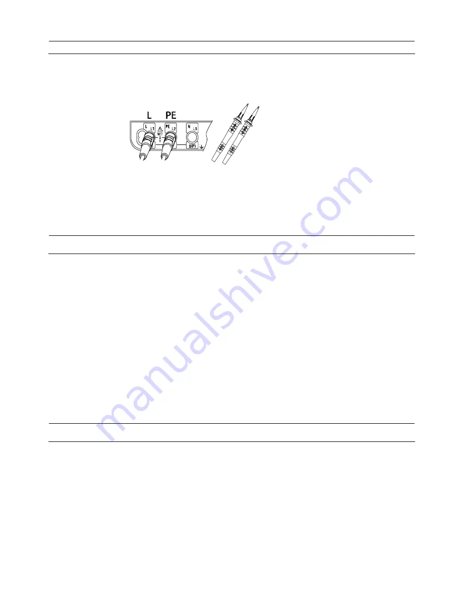
2. Insert the Test Leads into the instrument. (Fig.47) 


3. Voltage value and frequency will be displayed on the LCD when applying AC voltage. 

Note : A message “DC V” may be displayed when measuring AC voltages with frequencies 

out of the range 45Hz - 65Hz. 


14. TOUCH PAD 


1. The touch pad measures the potential between the operator and the tester’s PE terminal. 

A message “PE HiV” is displayed on the LCD with the audible buzzer if a potential 

difference of 100V or more is present between the operator and the PE terminal at touching 

the Touch pad. 


2. Touch Pad function can be enabled and disabled (ON / OFF); refer to ”6. Configuration” in 

this manual and select ON or OFF. In case that OFF is selected, a warning for “PE HiV” 

does not appear and the buzzer does not sound. 

* Initial value: ON 

Note :


A message “PE HI V” may be displayed when testing inverters or measuring voltages 

containing high frequencies even if a user isn’t touching with the Touch Pad.


15. BACK LIGHT 


Pressing the Back Light Button selects Backlight ON / OFF. Backlight automatically turns off   

in 60 sec after it turns on. Backlight at powering on the instrument can be set either ON or   

OFF. Refer to “6. Configuration” in this manual how to select ON / OFF. 

Fig.47 

Содержание KEW 6016

Страница 1: ...INSTRUCTION MANUAL MULTI FUNCTION TESTER KEW 6016...

Страница 2: ...2 Damage to voltage sensitive equipment 22 8 3 Preparation for measurement 23 8 4 Insulation resistance measurement 23 9 LOOP PSC PFC test 26 9 1 Principles of measurement of fault loop impedance and...

Страница 3: ...W6016 incorporates Anti Trip Technology ATT which electronically bypasses RCDs when performing loop impedance tests This saves time and money by not having to take the RCD out of the circuit during te...

Страница 4: ...k may become live for the duration of the test 5 Never open the instrument case except for fuse and battery replacement and in this case disconnect all leads first because dangerous voltages are prese...

Страница 5: ...button is depressed or in lock down position the test in progress will be halted 13 Always check the test lead resistance before carrying out tests This ensures the leads are ok before taking measure...

Страница 6: ...ure 3 Touch Pad Checks the electrical potential at the PE terminal 4 Power Switch Power Switch 5 Function Switch Function setting F1 F4 6 Display LCD Dot Matrix LCD 160 W X240 H 7 Insulation resistanc...

Страница 7: ...OLTS N Neutral for LOOP PSC PFC RCD L1 Line1 L2 Line2 2 Terminal Name for PHASE ROTATION L3 Line3 H C Terminal for auxiliary earth spike current E Terminal for the earth under test 3 Terminal Name for...

Страница 8: ...uxiliary Earth Spikes 5 Test Lead Carry pouch x1 6 Carrying Bag x1 7 Instruction Manual x1 8 Shoulder Strap x1 9 Buckle x2 10 Battery x8 11 Model8212USB with PC Software KEW Report Blue Neutral Fig 3...

Страница 9: ...blow at live working With this function a fuse rarely blow while measuring continuity on live conductors Continuity Null Allows automatic subtraction of test lead resistance from continuity measuremen...

Страница 10: ...the RCD mode to obtain the maximum trip time of an RCD for the test selected UL value selector Select UL limit of contact voltage 25V or 50V Where Uc contact voltage exceeds UL value at RCD testing U...

Страница 11: ...o Ranging 0 19 99M 2 rdg 6dgt 20 200M 5 rdg 6dgt 500V 25 0 1mA or greater 500k 20 200 2000M Auto Ranging 1000V 20 0 1mA or greater 1M 20 200 2000M Auto Ranging 0 199 9M 2 rdg 6dgt 200 2000M 5 rdg 6dgt...

Страница 12: ...dance specification and measured voltage specification 5 at 230V RCD Accuracy Trip Current Function Rated Voltage AC Type A Type Trip Time X1 2 8 2 10 0 X1 2 8 0 10 X5 2 8 0 10 Ramp 230V 10 15 50 60Hz...

Страница 13: ...X5 S A 410 410 410 n a n a n a AC n a G A Goes up by 10 from 20 to 110 300ms 10 times n a AC n a Trip Current Duration ms Ramp S A Goes up by 10 from 20 to 110 500ms 10 times n a Earth Measuring Freq...

Страница 14: ...s than 2000m 5 2 Operating error Continuity EN61557 4 Operating range compliant with EN61557 4 operating error Maximum percentage operating error 0 20 1999M 30 The influencing variations used for calc...

Страница 15: ...3 8V Harmonics 5 of 3rd harmonic at 0 phase angle 5 of 5th harmonic at 180 phase angle 5 of 7th harmonic at 0 phase angle D C quantity 0 5 of the nominal voltage RCD EN61557 6 Function Operating error...

Страница 16: ...g conditions except where otherwise stated 1 Ambient temperature 23 5 C 2 Relative humidity 45 to 75 3 Position horizontal 4 AC power source 230V 50Hz 5 DC power source 12 0 V ripple content 1 or less...

Страница 17: ...IP40 EMC EN 61326 EN55022 24 This manual and product may use the following symbols adopted from International Safety Standards CAT III Measurement category CAT III applies to Primary electrical circu...

Страница 18: ...PE Hi V Caution Presence of high voltage between NEUTRAL EARTH during ATT measurement ATT function should be disabled to continue measurements Uc UL Caution Uc at RCD measurement is exceeding the pre...

Страница 19: ...Press the F1 F4 Button to change following setting Parameter Selection Initial value F1 UL value 25V 50V 50V F2 Touch Pad ON OFF ON F3 Back Light ON OFF OFF F4 Language EN FR PL IT ES RU EN 4 Press t...

Страница 20: ...is provided with a continuity null feature which allows automatic compensation for any test lead resistance You should only use the test leads supplied with the instrument Operation of Function Switc...

Страница 21: ...e leads have been zeroed 6 Connect the test leads to the circuit whose resistance is required see Fig 14 for a typical connection arrangement having first made sure that the circuit is not live Note t...

Страница 22: ...2 Buzzer function Use F2 Button to enable disable the 2 Buzzer The buzzer sounds when measured resistance is 2 or less while this function is enabled The buzzer does not sound if it is disabled Fig 14...

Страница 23: ...eakage current This current is made up of three components which are 1 capacitive current 2 conduction current and 3 surface leakage current 8 1 2 Capacitive Current The insulation between conductors...

Страница 24: ...all Where the surfaces are wet and or dirty the surface leakage current may be significant If it becomes large enough it may constitute a flashover between the conductors Whether this happens depends...

Страница 25: ...charged If the wiring system is wet and or dirty the surface leakage component of the leakage current will be high resulting in low insulation resistance reading In the case of a very large electrical...

Страница 26: ...uit to be tested is not live Live Circuit warning is displayed if the instrument is connected to a live circuit but test the circuit as well Operation of Function Switch F1 N A F2 N A F3 N A 250V M F4...

Страница 27: ...if the circuit resistance is greater than 20M the instrument will autorange to the 200M range If it is greater than 200M at the 500V or 1000V range it will autorange to the 2000M range 8 When testing...

Страница 28: ...ch while the test button is depressed as this may damage the instrument Always release the test button first after testing before removing the test leads from the circuit This is to ensure that charge...

Страница 29: ...specified or appropriate for the over current protective device installed in the circuit The KEW6016 takes a current from the supply and measures the difference between the unloaded and loaded supply...

Страница 30: ...32A at 230 400V AC 1000 ms for distribution circuits and circuits over 32A at 230 400V AC The compliance with the above rules shall be verified by 1 Measurement of the resistance Ra of the local earth...

Страница 31: ...must be tested Please refer to RCD TESTS section TN System For TN systems the earth fault loop impedance is the sum of the following impedances Impedance of the power transformer secondary winding Im...

Страница 32: ...d circuits over 32A at 230 400V AC The compliance with the above rules shall be verified by 1 Measurement of the fault loop impedance Zs by Loop tester 2 Verification of the characteristics and or the...

Страница 33: ...1 44 125 1 84 250 0 92 500 0 46 32 125 1 84 221 1 04 160 1 44 320 0 72 640 0 36 40 170 1 35 200 1 15 400 0 57 800 0 29 50 221 1 04 250 0 92 500 0 46 1000 0 23 63 280 0 82 315 0 73 630 0 36 1260 0 18...

Страница 34: ...urement with the exception that the measurement is carried out between line and neutral or line and line Prospective short circuit or fault current at any point within an electrical installation is th...

Страница 35: ...your distributor Operation of Function Switch LOOP F1 Switches measurement mode L PE or L N L L F2 ATT setting on or off F3 N A L PE ATT ON 230V 50 0Hz L PE L N F4 N A PSC PFC F1 Switches measurement...

Страница 36: ...is to measure LOOP resistances without tripping the RCDs rated at 30mA or more ATT ON is displayed while it is activated 2 Wiring Check After the connection ensure that the symbols for Wiring check o...

Страница 37: ...Impedance and PSC Press the Mode Switch F1 and select L N L L or PSC Connect the blue N lead of the Model7188 to the neutral of the distribution board the brown L lead to one line of the distribution...

Страница 38: ...disable the ATT function and make measurement When a large contact voltage exists in the circuit under test N PE HiV is displayed on the LCD and no measurement can be made In this case disable the AT...

Страница 39: ...V 50 0Hz L PE L N ATT ON PSC A 230 V L N 50 0Hz L PE L N Fig 33 Connection for Line Neutral measurement Fig 34 Connection for Line Line measurement Fig 32 Connection for distribution PSC A 400 V L L 5...

Страница 40: ...the most frequently used on electrical installations RCD type A will trip when presented with residual sinusoidal alternating currents similar to type AC and residual pulsating direct currents DC whet...

Страница 41: ...and 5I n Type of RCD I n 5I n General G 300ms max allowed value 40ms max allowed value 500ms max allowed value 150ms max allowed value Selective S 130ms min allowed value 50ms min allowed value Exampl...

Страница 42: ...ith the impedance measured 10 3 Operating Instructions for RCD 10 3 1 Initial Checks to be carried out before any testing 1 Preparation Always inspect your test instrument and lead accessories for abn...

Страница 43: ...the details of RCD type 6 5 Press F4 to select phase at which the test current should start 7 6 7 except for Uc measurement UL value change As a UL value 25V or 50V is selectable Refer to 6 Configurat...

Страница 44: ...switch to change the phase and repeat step 1 3 Change the phase again and repeat step 1 b Auto Test Measurements are automatically performed under the Auto Test function in the following sequence X1...

Страница 45: ...y influence the measurement Special conditions of RCDs of a particular design for example S type should be taken into consideration The earth electrode resistance of a measuring circuit with a probe s...

Страница 46: ...between terminals E H C in earth resistance function Take enough caution to avoid electric shock hazard CAUTION When measuring earth resistance do not apply voltage between measuring terminals 1 Selec...

Страница 47: ...ach other the reading of the instrument may be affected by induction When connecting the probes make sure that they are separated If earth resistance of auxiliary earth spikes is too large it may resu...

Страница 48: ...to a circuit Fig 44 L1 L3 L2 4 Results are displayed as follows When a message No 3 phase system or is displayed the circuit may not be a 3 phase system or a wrong connection may have been made Check...

Страница 49: ...of 100V or more is present between the operator and the PE terminal at touching the Touch pad 2 Touch Pad function can be enabled and disabled ON OFF refer to 6 Configuration in this manual and selec...

Страница 50: ...s to enter into MEMORY MODE 3 Press to enter into SAVE MODE 4 Make setting for following items 1 CIRCUIT No 2 BOARD No 3 SITE No 4 DATA No Press the SELECT Button to choose the parameter to change CIR...

Страница 51: ...ayed for about 2 sec on the LCD and then returns to the start screen Saving completes Normal mode Returns to Normal mode once data save completes Measurement mode 250V M 18 52 Fig 48 4 Fig 48 5 Fig 48...

Страница 52: ...nce 1 Press to enter into MEMORY MODE 2 Press to enter into RECALL MODE 3 Press Up or DOWN and select Data No Fig 49 1 Fig 49 2 Fig 49 3 Keep the UP DOWN Key pressed down until a buzzer sounds to skip...

Страница 53: ...MEMORY MODE 2 Press to enter into DELETE MODE 3 Press Up or DOWN and select Data No 2 Press to enter into ALL DELETE MODE 4 Press DELETE Confirmed 3 Press ALL DELETE Confirmed ALL DELETE DELETE Fig 5...

Страница 54: ...ETE Confirmed 6 Returns to Normal mode when selected data deleted Measurement mode 4 Returns to Normal mode when selected data is deleted Measurement mode Fig 50 5 Fig 50 6 Fig 50 7 Fig 50 8 Fig 50 9...

Страница 55: ...KEW6016 as shown in Fig 52 Test Leads should be removed from the KEW6016 at this time 3 Power on the KEW6016 Any function is OK 4 Start special software KEW Report on your PC and set the communicatio...

Страница 56: ...eat damage 17 2 The test button may be turned clockwise to lock it down In this auto mode when using distribution board lead Model7188 tests are conducted by simply disconnecting and reconnecting the...

Страница 57: ...e in the continuity test mode first disconnect the test leads from the instrument Next remove the battery cover take out the fuse and test its continuity with another continuity tester If it has faile...

Страница 58: ...ure that 1 The leads have been checked for continuity and signs of damage 2 The continuity mode fuse situated in the battery compartment has been checked 3 The batteries are in good condition Please r...

Страница 59: ...h the Buckle to the KEW6016 as shown in Fig 54 2 How to install the Strap belt 3 How to fasten the Strap belt Match the hole of the Buckle and the protrusion at the side face of KEW6016 and slide it u...

Страница 60: ...DISTRIBUTOR Factory Ehime...

Отзывы: