2H4
1-5-22
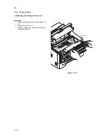
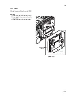
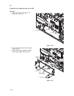
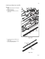
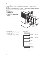
(2) Detaching and refitting the power source PWB
Procedure
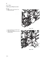
1. Remove the left cover (See page 1-5-4).
2. Remove four connectors.
Figure 1-5-30
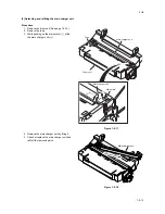
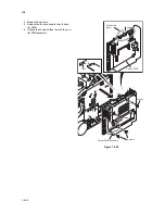
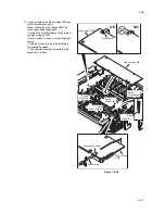
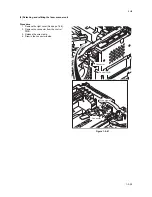
3. Remove four P tight screws, two screws and
ground terminal.
4. Remove the power source PWB assembly
from the high voltage PWB’s connector.
Figure 1-5-31
Connector
Connector
Connector
Connector
Power source
PWB assembly
P tight screws
P tight screws
Ground
terminal
Screws
Connector
(YC201)
High voltage PWB
Connector
(YC103)
Содержание ECOSYS FS-1350DN
Страница 1: ...SERVICE MANUAL Published in October 2008 842H4010 2H4SM060 First Edition FS 1350DN ...
Страница 3: ...Revision history Revision Date Replaced pages Remarks ...
Страница 4: ...This page is intentionally left blank ...
Страница 10: ...This page is intentionally left blank ...
Страница 18: ...2H4 1 1 6 This page is intentionally left blank ...
Страница 21: ...2H4 1 2 3 1 Removing the tapes Procedure 1 Remove three tapes Figure 1 2 3 Tape Tape Tape ...
Страница 24: ...2H4 1 2 6 This page is intentionally left blank ...
Страница 57: ...2H4 1 5 5 5 Unhook seven hooks and then remove the left cover Figure 1 5 6 Left cover Hooks ...
Страница 104: ...2H4 2 1 14 Figure 2 1 21 Paper exit section block diagram EXITN Fuser unit Exit sensor Control PWB YC333 3 ...
Страница 106: ...2H4 2 1 16 This page is intentionally left blank ...
Страница 110: ...2H4 2 2 4 This page is intentionally left blank ...
Страница 118: ...2H4 2 3 8 This page is intentionally left blank ...
Страница 121: ......
Страница 122: ......


