2H4
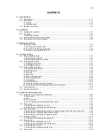
(1) Detaching and refitting the fuser unit...............................................................................................1-5-16
(2) Switching the fuser pressure ...........................................................................................................1-5-18
1-5-8 PWBs ....................................................................................................................................................1-5-19
(1) Detaching and refitting the control PWB .........................................................................................1-5-19
(2) Detaching and refitting the power source PWB...............................................................................1-5-22
(3) Detaching and refitting the high voltage PWB.................................................................................1-5-24
1-5-9 Others ...................................................................................................................................................1-5-28
(1) Detaching and refitting the main motor ...........................................................................................1-5-28
(2) Detaching and refitting the laser scanner unit .................................................................................1-5-29
(3) Detaching and refitting the eraser lamp (PWB)...............................................................................1-5-31
(4) Direction of installing the left cooling fan motor and right cooling fan motor ...................................1-5-32
1-6 Firmware
1-6-1 Downloading firmware ............................................................................................................................1-6-1
(1) Firmware files ....................................................................................................................................1-6-1
(2) Downloading the firmware from the USB memory ............................................................................1-6-2
(3) Downloading the firmware from the memory card.............................................................................1-6-4
2-1 Mechanical Construction
2-1-1 Paper feed/conveying section.................................................................................................................2-1-1
(1) Cassette paper feed section..............................................................................................................2-1-1
(2) MP tray paper feed section ...............................................................................................................2-1-2
(3) Paper conveying section ...................................................................................................................2-1-3
2-1-2 Drum section...........................................................................................................................................2-1-4
(1) Drum section .....................................................................................................................................2-1-4
(2) Main charger unit...............................................................................................................................2-1-5
2-1-3 Expose section........................................................................................................................................2-1-6
(1) Laser scanner unit.............................................................................................................................2-1-6
2-1-4 Developing section..................................................................................................................................2-1-8
2-1-5 Transfer/separation section ....................................................................................................................2-1-9
2-1-6 Cleaning section ...................................................................................................................................2-1-10
2-1-7 Fuser section ........................................................................................................................................2-1-11
2-1-8 Paper exit section .................................................................................................................................2-1-13
2-1-9 Duplex/conveying section .....................................................................................................................2-1-15
2-2 Electrical Parts Layout
2-2-1 Electrical parts layout..............................................................................................................................2-2-1
(1) PWBs ................................................................................................................................................2-2-1
(2) Switches and sensors .......................................................................................................................2-2-2
(3) Other electrical components..............................................................................................................2-2-3
2-3 Operation of the PWBs
2-3-1 Power source PWB.................................................................................................................................2-3-1
2-3-2 Control PWB ...........................................................................................................................................2-3-3
2-4 Appendixes
2-4-1 Appendixes .............................................................................................................................................2-4-1
(1) Wiring diagram ..................................................................................................................................2-4-1
(2) Repetitive defects gauge...................................................................................................................2-4-2
Содержание ECOSYS FS-1350DN
Страница 1: ...SERVICE MANUAL Published in October 2008 842H4010 2H4SM060 First Edition FS 1350DN ...
Страница 3: ...Revision history Revision Date Replaced pages Remarks ...
Страница 4: ...This page is intentionally left blank ...
Страница 10: ...This page is intentionally left blank ...
Страница 18: ...2H4 1 1 6 This page is intentionally left blank ...
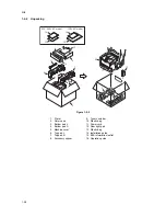
Страница 21: ...2H4 1 2 3 1 Removing the tapes Procedure 1 Remove three tapes Figure 1 2 3 Tape Tape Tape ...
Страница 24: ...2H4 1 2 6 This page is intentionally left blank ...
Страница 57: ...2H4 1 5 5 5 Unhook seven hooks and then remove the left cover Figure 1 5 6 Left cover Hooks ...
Страница 104: ...2H4 2 1 14 Figure 2 1 21 Paper exit section block diagram EXITN Fuser unit Exit sensor Control PWB YC333 3 ...
Страница 106: ...2H4 2 1 16 This page is intentionally left blank ...
Страница 110: ...2H4 2 2 4 This page is intentionally left blank ...
Страница 118: ...2H4 2 3 8 This page is intentionally left blank ...
Страница 121: ......
Страница 122: ......


