2H4
2-3-1
2-3 Operation of the PWBs
2-3-1 Power source PWB
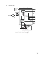
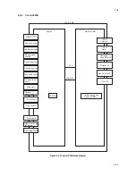
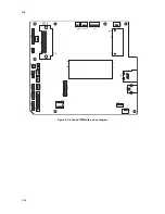
Figure 2-3-1 Power source PWB block diagram
+24V1
SLEEP
+24V1
+24V2
FAN
+3.3V2
ZCROSS
HEATN
THERM
Power source PWB
Left
cooling
fan motor
Fuser thermistor
Fuser thermal cutout
Fuser unit
Switching
regulator
circuit
Zero cross
signal circuit
AC input
Interlock
switch
Power switch
Fuser heater
lamp control
circuit
Fuser
heater lamp
Содержание ECOSYS FS-1350DN
Страница 1: ...SERVICE MANUAL Published in October 2008 842H4010 2H4SM060 First Edition FS 1350DN ...
Страница 3: ...Revision history Revision Date Replaced pages Remarks ...
Страница 4: ...This page is intentionally left blank ...
Страница 10: ...This page is intentionally left blank ...
Страница 18: ...2H4 1 1 6 This page is intentionally left blank ...
Страница 21: ...2H4 1 2 3 1 Removing the tapes Procedure 1 Remove three tapes Figure 1 2 3 Tape Tape Tape ...
Страница 24: ...2H4 1 2 6 This page is intentionally left blank ...
Страница 57: ...2H4 1 5 5 5 Unhook seven hooks and then remove the left cover Figure 1 5 6 Left cover Hooks ...
Страница 104: ...2H4 2 1 14 Figure 2 1 21 Paper exit section block diagram EXITN Fuser unit Exit sensor Control PWB YC333 3 ...
Страница 106: ...2H4 2 1 16 This page is intentionally left blank ...
Страница 110: ...2H4 2 2 4 This page is intentionally left blank ...
Страница 118: ...2H4 2 3 8 This page is intentionally left blank ...
Страница 121: ......
Страница 122: ......


