Connection
11
If the LED is on, the connection is correct. If the LED is off, the link is not connected. This
may be caused by incorrect connection of the TX and RX ports. In this case, swop the two
connectors at one end of the fibers.
Caution:
The device uses laser to transmit signals in fibers. The laser meets the requirements of level 1
laser products. Routine operation is not harmful to your eyes, but do not look directly at the
fiber port when the device is powered on.
If the defined transmission distance of an SFP module is longer than 60km, do not use a short
fiber (<20km) for connection. If such a short fiber is used, the module will be burned.
4.2.2 Gigabit SFP Electrical Module
Figure 10 Gigabit SFP Electrical Module
How to Connect the SFP Electrical Module
Insert the SFP electrical module into the SFP slot in the switch, and then insert the RJ45
connector of the twisted pair into the SFP module.
Figure 11 Connecting the SFP Electrical Module
4.3 1000Base-X, 10/100/1000Base-T(X) Combo port
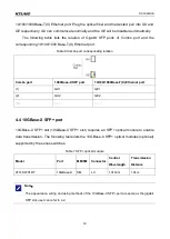
As shown in following table, the 1000Base-X, 10/100/1000Base-T(X)Combo port consists of
one 1000Base-X SFP port(GX) and one 10/100/1000Base-T(X) Ethernet port, and only one
of the two ports can be used at one time, and the 1000Base-X SFP port has priority over


